
Installation Instructions


g037192
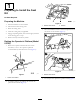
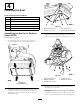
Figure22
1.Nut
4.Ringterminal(machine
harness)
2.Washers5.Bolt
3.Bracket(horn)6.Ringterminal(relay
harness)
5.Assembletheringterminaloftherelayharness,the
ringterminalofthemachinewireharness,andthe
horntothechassiswiththebolt,washers,andnutthat
youremovedinstep4.
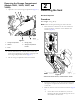
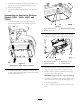
6.Routethe2-socketconnectorfortherelayharness
(whiteandblackwires)andthethroughtheholeinthe
platformlocatedbehindtheseat(Figure23).
g037059
Figure23
1.Hole(bottomofplatform)
2.Relayharnessandkit
harness
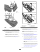
7.Atthebackoftheseat,locatethe2-pinconnectorfor
theseatswitch(yellowandgreywires)andconnectit
tothe2-socketconnectoroftherelayharness(white
andblackwires)asshowninFigure24.
g037180
Figure24
1.2-blade
connector—seat-air-suspension
3.2-pinconnector—seat
switch(yellowandgrey
wires)
2.2-socketconnector—350
cm(137-3/4inches)kit
wireharness(blackand
redwires)
4.2-socketconnector—relay
harness(whiteandblack
wires)
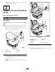
ConnectingtheSeat-Air-Suspension
WireHarness(Model02750)
1.Locatethe350cm(137-3/4inches)wireharness
(withoutaringterminal)asshowninFigure25.
g037194
Figure25
1.Wire(black)5.Wire(red)
2.Socketterminal(black
wire)
6.Socketterminal(redwire)
3.Piggy-backfeature(socket
terminal)
7.Posilockfeature(socket
terminal)
4.2-socketconnector
2.Atthebottomoftheplatform,routethe2-socket
connector(blackandredwires)forthe350cm
(137-3/4inches)kitwireharnessalongtherelay
harnessandthroughtheholeintheplatformlocated
10