Form No. 3440-878 Rev A Vinyl or Fabric Air Ride Seat Kit LT2240 Compact Triple 4-Wheel Drive Turf Mower, LT3340 Triple Reel Mower, or LT-F3000 Triple Flail Mower Model No. 02875—Serial No. 400000000 and Up Model No. 02876—Serial No. 400000000 and Up Installation Instructions Installation Loose Parts Use the chart below to verify that all parts have been shipped. Procedure Description Use Qty. 1 2 No parts required – Prepare the machine.
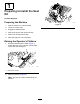
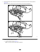
1 Preparing to Install the Seat Kit No Parts Required Preparing the Machine 1. Park the machine on a level surface. 2. Lower the cutting units. 3. Engage the parking brake. 4. Shut off the engine and remove the key. 5. Wait for all moving parts to stop. 6. Allow the engine to cool completely. g290372 Figure 2 Raising the Operator’s Platform 1. Move the platform-latch handle (Figure 1) toward the front of the machine until the latch hooks clear the locking bar. g290373 Figure 1 1.
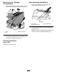
Disconnecting the Battery Removing the Storage Compartment 1. 1. At the left side of the operator’s platform, open the door of the storage compartment (Figure 3). Loosen the forward nut of the negative battery-cable terminal (Figure 4). g344733 Figure 4 1. Nut (negative battery-cable terminal) 2. g328513 Figure 3 1. Washer Lift the negative battery cable from the battery post (Figure 4). Note: Position the negative-battery cable where it cannot contact the negative battery post. 3.
3. 2 Remove the boot from the seat base as follows (Figure 6). A. Removing the Existing Seat At the sides of the seat-base boot, locate its mounting tabs that protrude through the slot in the channel of the seat base. Model 31654 No Parts Required Procedure Seat weight: 38 kg (84 lb) Note: Have another person help you remove the seat or use a suitable crane. 1. Disconnect the connector for the seat-switch wire harness from the connector of the machine wire harness (Figure 5).
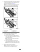
4. While supporting the seat, remove the 4 washers (8 mm) and 4 locknuts (8 mm) that secure the seat to the seat platform (Figure 7). Note: Do not remove the 4 bolts (8 x 25 mm) from the holes in the seat and seat platform. g036780 Figure 7 1. Bolt (8 x 25 mm) 3. Locknut (8 mm) 2. Seat platform 4. Washer (8 mm) 5. Lower the operator’s platform as follows: A. Lower the platform carefully. B.
3 Removing the Existing Seat Models 31657 and 31659 No Parts Required Procedure Seat weight: 38 kg (84 lb) Note: Have another person help you remove the seat or use a suitable crane. 1. Disconnect the main wire-harness connector from the control-arm harness (Figure 8). Rotate the collar and pull the connector to remove. Important: Cover and protect the electrical connectors to prevent damage. g343901 Figure 8 2. Disconnect the seat-switch harness from the seat and leave it on the platform.
3. Remove the boot from the seat base as follows (Figure 9). A. At the sides of the seat-base boot, locate its mounting tabs that protrude through the slot in the channel of the seat base. g037076 g037047 Figure 9 1. Tabs (seat-base boot) B. 2. Slots (seat-base channel) Pull each tab along the slot until the tab is over the hole and then pull the tab out and away from the seat-base channel. Note: Pull the boot forward or rearward depending on which tab you are the removing. C.
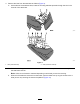
4. While supporting the seat, remove the 4 locknuts (8 mm) that secure the seat to the seat platform (Figure 10). Do not remove the 4 bolts (8 x 25 mm) from the holes in the seat and seat platform. g343902 Figure 10 5. Lower the operator’s platform as follows: A. Lower the platform carefully (Figure 11). Note: The gas lift cylinder helps support the platform.
g290371 Figure 11 B. As the platform nears the fully lowered position, move the platform-latch handle (Figure 12) toward the front of the machine. Note: This ensures that the latch hooks clear the locking bar. g290369 Figure 12 2. Locking bar 1. Platform-latch handle C. Fully lower the platform and move the platform-latch handle toward the rear of the machine until the latch hooks fully engage the locking bar (Figure 13). g290370 Figure 13 1. Platform-latch handle 6.
3. 4 Assemble the seat belt onto the new seat and install the previously removed armrest using the previously removed nut (Figure 15). Set the armrest to be the same height as the other side. Preparing the New Seat 4. Model 31654 Torque the seat belt bolts to 70 to 75 N∙m (52 to 55 ft-lb) and install the covers (Figure 15). Parts needed for this procedure: 1 Seat and suspension assembly Procedure 1.
5 Preparing the New Seat Models 31657 and 31659 Parts needed for this procedure: 1 Seat and suspension assembly Removing the Control Arm and Seat Belt from the Seat 1. Place the seat and control arm onto a bench. 2. Remove the seat cushion to gain access to the flange nut securing the control arm to the seat (Figure 16).
3. Remove the plastic cover on the left side and loosen the bolt to remove the seat-belt retainer from the seat (Figure 17).
4. Ensure that the control arm is supported sufficiently before removing. 5. Remove the existing hex-head bolt (7/16 x 2 inches), 2 washers, seat belt, and spacer (Figure 18). Retain the hex-head bolt (7/16 x 2 inches), 2 washers, seat belt, and spacer for later installation. g344019 Figure 18 1. Control-arm support 3. Washer 5. Seat belt 2. Hex-head bolt (7/16 x 2 inches) 4. Washer 6. Spacer 6. Remove the front control arm support plate from the seat.
7. Remove the hex-head bolt (8 x 10 mm), coupling hex nut (8 mm), and washer (8 mm) from the top of the seat arm (Figure 19). Retain the hex-head bolt (8 x 10 mm), coupling hex nut (8 mm), and washer (8 mm) for later installation. g345727 Figure 19 Installing the Control Arm and Seat Belt to the New Air Ride Seat 1. Remove the 3 Phillips-head screws securing the seat cushion and remove the seat cushion (Figure 20). This allows access to secure the control arm to the seat. g344859 Figure 20 2.
3. Locate the previously removed control arm and brackets. 4. Secure the previously removed fasteners as shown in Figure 21. 5. Apply Loctite® 243 to the hex-head bolt (7/16 x 2 inches) and torque the hex-head bolt (7/16 x 2 inches) to 70 to 75 N∙m (52 to 55 ft-lb). g344019 Figure 21 1. Control-arm support 3. Previously removed washer 5. Previously removed seat belt 2. Previously removed hex-head bolt (7/16 x 2 inches)—apply Loctite 243 to this bolt. 4. Previously removed washer 6.
6 Installing the Seat Model 31654 Parts needed for this procedure: 4 Locknut (8 mm) 4 Hex-head bolt (8 x 25 mm) g345847 Figure 23 Procedure 1. 1. Hex-head bolt (8 x 25 mm) 2. Flange (seat-bottom plate) At the bottom plate of the new seat, locate the seat-mounting holes for your machine (Figure 22). 3. Align the 4 hex-head bolts (8 x 25 mm) of the new seat with the holes in the operators platform (Figure 24). g345846 Figure 24 1. Hex-head bolt (8 x 25 mm) 3. Locknuts (8 mm) 2.
7 Installing the Seat Models 31657 and 31659 Parts needed for this procedure: 4 Hex-head bolt (8 x 25 mm) 4 Locknut (8 mm) Procedure 1. At the bottom plate of the new seat, locate the seat-mounting holes for your machine (Figure 25).
2. Secure the seat assembly to the platform using the 4 hex-head bolts (8 x 25 mm) and 4 locknuts (8 mm) as shown in Figure 26. g345728 Figure 26 1. Hex-head bolt (8 x 25 mm) 2. Locknut (8 mm) 3. Fully raise the platform. 4. Torque the 4 locknuts (8 mm) to 27 N∙m (20 ft-lb).
4. 8 Insert the standard fuse (10 A) into the 5th fuse position from the left (Figure 28) of the fuse block as follows: Note: Ensure that the fuse is fully seated. Connecting the Electrical Components Parts needed for this procedure: 1 Standard fuse (10A)—Model 31654 1 Mini fuse (10 A)—Models 31657 and 31659 Model 31654 1. g037201 Figure 28 Locate the connector labeled AIR-RIDE on the seat behind the rubber boot. 1.
Models 31657 and 31659 1. Connect the main wire-harness connector to the control arm that you disconnected in 3 Removing the Existing Seat (page 6). 2. Locate the connector labeled AIR-RIDE on the seat behind the rubber boot. Locate the air-ride seat connector on the main wire harness breakout and install the connector. Note: The breakout of the main wire harness is located by the seat. 3. Connect the seat-switch connector. 4.
Installing the Storage Compartment 9 Completing the Seat Kit Installation 1. Align the holes on the bottom of the storage compartment with the holes in the chassis brackets. 2. Assemble the storage compartment to the machine with the 3 knobs and 3 washers (Figure 31). No Parts Required Connecting the Battery 1. Assemble the terminal of the negative battery cable (Figure 30) onto the negative battery post. g328512 Figure 31 g344733 Figure 30 1. Nut (negative battery-cable terminal) 2. 1.
Lowering the Operator’s Platform 3. WARNING Fully lower the platform and move the platform-latch handle toward the rear of the machine until the latch hooks fully engage the locking bar (Figure 34). Operating the machine with the platform unlatched may cause you to lose control of the machine, resulting in serious injury to you and bystanders. Never operate the machine without first checking that the operator platform latching mechanism is fully engaged and in good working order. 1.
Product Overview Weight and Height Adjustment Lever Use this lever to adjust to the proper weight of the operator (Figure 35). Pull up the lever to increase the air pressure and push down to decrease the air pressure. The proper adjustment is correct when the weight and height gauge is in the green region. Controls Seat Controls Also use this lever to adjust the height of the seat. Position the suspension anywhere within the green region on the gauge to adjust the height.
Maintenance Greasing the Seat Suspension Mechanism Service Interval: Yearly 1. Pull back the rubber boot from the channel of the seat base. 2. Apply good quality grease to all pivot points of the suspension mechanism. 3. Install the boot onto the channel of the seat base. Maintaining the Seat Belt There are no field-serviceable parts on the seat belt. If it shows signs of wear, damage, or malfunction, replace the seat belt assembly.
Notes:
Notes:
EEA/UK Privacy Notice Toro’s Use of Your Personal Information The Toro Company (“Toro”) respects your privacy. When you purchase our products, we may collect certain personal information about you, either directly from you or through your local Toro company or dealer.
The Toro Warranty Two-Year or 1,500 Hours Limited Warranty Parts Conditions and Products Covered The Toro Company warrants your Toro Commercial product (“Product”) to be free from defects in materials or workmanship for 2 years or 1,500 operational hours*, whichever occurs first. This warranty is applicable to all products with the exception of Aerators (refer to separate warranty statements for these products).