Form No. 3404-141 Rev A Mauser KS-534 Full Safety Cab CT2240/LT3340/LT-F3000 and Groundsmaster® 3400 Mowers Model No. 02890—Serial No. 316000001 and Up Register at www.Toro.com.
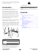
This product complies with all relevant European directives. For details, please see the Declaration of Incorporation (DOI) at the back of this publication. Figure 2 1. Safety alert symbol Introduction This manual uses 2 words to highlight information. Important calls attention to special mechanical information and Note emphasizes general information worthy of special attention. This manual provides instructions for the operation and operator maintenance of the Full Safety Cab.
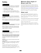
Maximum Slope Angles of Mowers with Cab Safety WARNING This cab can be fitted to the mowers listed at the front of this document. When fitted with a cab, each mower model has a different maximum slope angle and this is stated on the decal located on the lid of the storage pod on the left of the machine. Refer to Safety and Instructional Decals (page 4) for the correct maximum slope angle decal for your machine when fitted with a cab.
Sound Pressure Level LT-F3000 Model CT2240 This unit has a sound pressure level at the operator’s ear of 86 dBA, which includes an Uncertainty Value (K) of 2 dBA. This unit has a sound pressure level at the operator’s ear of 83 dBA, which includes an Uncertainty Value (K) of 2 dBA. Sound pressure level was determined according to the procedures outlined in EN ISO 5395. Sound pressure level was determined according to the procedures outlined in EN ISO 5395.
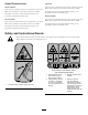
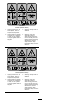
111-9833 CT2240 (Model 30654) 1. Tipping hazard—turn at slow speeds; drive on slopes at slow speeds. 3. Warning—always wear a seatbelt. 2. Tipping hazard—operate on slopes of 17 degrees or less; do not operate on slopes greater than 17 degrees. 4. Warning—read the Operator's Manual; wear hearing protection; remove the key from the ignition before performing maintenance; thrown object hazard—keep bystanders away from the machine. 111-9834 LT3340 (Model 30657) 1.
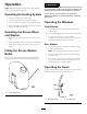
Product Overview Controls Heater/Blower Controls The controls are mounted on the right side in the roof lining. Figure 5 2 1. Interior light switch 1 Front Window Handle (2) You can open the front window for ventilation. There are 2 handles (Figure 6). 1 g020347 Figure 3 1. Blower speed switch 3. Air-conditioner switch (air conditioning optional) 2. Temperature controller g018406 Figure 6 Screen Wiper and Washer Switch 1.
Operation WARNING Failure to use washer fluid with antifreeze protection in cold weather could result in impaired windscreen vision and increase the risk of injury or accident. Note: Determine the left and right sides of the machine from the normal operating position. If you operate your machine in temperatures below 5°C (40°F), use washer fluid with antifreeze protection. Operating the Heating System 1. Set the air conditioner switch to Off. 2. Set the fan speed switch to the desired speed. 3.
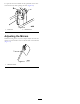
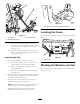
To open the door from inside the cab, pull back on the door lock release lever while opening the door (Figure 10). Figure 10 1. Door lock 2. Release lever Adjusting the Mirrors While the sitting in the seat, have a helper adjust the side-view mirrors to attain the best view around the side of the machine (Figure 11). 1 g020380 Figure 11 1.
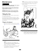
Maintenance Note: The built-in gas springs assist in raising the cab in a controlled manner and stop it when it is fully raised. 4. With the cab fully raised, install the safety support bracket as follows: WARNING Working on the machine without the safety support bracket increases your risk of injury. A. Remove the safety support bracket from the storage pod. Before carrying out maintenance underneath the operator platform and cab, ensure that the safety support bracket is installed.
1 g018408 Figure 15 1. Locking lever (2)—rotated downward (horizontal) Locating the Fuses Figure 14 1. Locking lever The cab fuses are located in the fuse box in the cab headliner (Figure 16). 3. Cross-beam bracket 2. Safety support bracket C. Once the safety support bracket is secured, rotated the cross-beam bracket toward the cab so that it rests against the bracket on the rear of the cab (Figure 14). D.
Notes: 11
Notes: 12
Notes: 13
Declaration of Incorporation The Toro Company, 8111 Lyndale Ave. South, Bloomington, MN, USA declares that the following unit(s) conform(s) to the directives listed, when installed in accordance with the accompanying instructions onto certain Toro models as indicated on the relevant Declarations of Conformity. Model No. 02890 Serial No.
International Distributor List Distributor: Agrolanc Kft Asian American Industrial (AAI) B-Ray Corporation Brisa Goods LLC Casco Sales Company Ceres S.A. CSSC Turf Equipment (pvt) Ltd. Cyril Johnston & Co. Cyril Johnston & Co. Fat Dragon Femco S.A. FIVEMANS New-Tech Co., Ltd ForGarder OU G.Y.K. Company Ltd. Geomechaniki of Athens Golf international Turizm Hako Ground and Garden Hako Ground and Garden Hayter Limited (U.K.) Hydroturf Int. Co Dubai Hydroturf Egypt LLC Irrimac Irrigation Products Int'l Pvt Ltd.
The Toro Total Coverage Guarantee A Limited Warranty Conditions and Products Covered The Toro® Company and its affiliate, Toro Warranty Company, pursuant to an agreement between them, jointly warrant your Toro Commercial product (“Product”) to be free from defects in materials or workmanship for two years or 1500 operational hours*, whichever occurs first. This warranty is applicable to all products with the exception of Aerators (refer to separate warranty statements for these products).