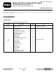
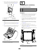
Form No. 3403-967 Rev A Road Light Kit including Brake Lights LT-F3000 Series Traction Unit Model No. 02918—Serial No. 316000001 and Up Installation Instructions This product complies with all relevant European directives. For details, please see the Declaration of Incorporation (DOI) at the back of this publication. Installation Loose Parts Use the chart below to verify that all parts have been shipped. Procedure Description Qty. Use 1 No parts required – Prepare the machine.
Procedure 3 4 5 Description Qty. 1 1 1 2 2 4 4 4 4 2 8 4 4 1 1 1 1 2 20 1 Left bracket Right bracket Light frame assembly Headlamp Headlamp cable Washer (M8) Washer (5/16 inch) Locknut (M8) Hex-head screw (M8 x 25 mm) Front light connector Washer (M12) Locknut (M12) Hex-head screw (M12) Light switch Hazard switch Direction-indicator switch Connector lead Adhesive reflector Cable tie Serial label 1 Preparing the Machine No Parts Required Procedure 1.
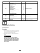
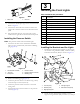
2 Installing the Rear Lights Parts needed for this procedure: 2 Bolt (M16 x 110 mm) 2 Locknut (M16) 1 Left light bracket assembly 1 Right light bracket assembly 1 Number-plate bracket 1 Number plate light 6 Washer (M6) 4 Locknut (M6) 2 Hex-head screw (M6 x 20 mm) 4. Disconnect the negative cable from the battery. 2 Setscrew (M3 x 16 mm) 2 Washer (M3) 5. Ensure that the ROPS pivot bolts and clamp bolts are in place and tight.
Installing the Fuses and the Number Plate Note: If a beacon kit is fitted to the machine, you may still use the pivot bolt location. 9. Feed all electrical cables down the front of the ROPS frame and onto the electrical mount panel. WARNING 10. Connect the connector lead to the main wiring loom of the machine (Figure 3). When drilling or carrying out other operations, always wear eye protection. 11.
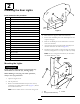
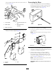
2. Drill an 8 mm (5/16 inch) diameter hole on the center of the bulkhead, 15 mm (5/8 inch) from the center line of the bulkhead (Figure 5). Figure 7 1. Hex-head screw (M6) 4. Number-plate bracket 2. Washer (M6) 5. Locknut (M6) 3. Number plate Figure 5 6. Feed the number plate light cable through the 8 mm (5/16 inch) hole in the bulkhead and install the light to the bracket using 2 setscrews (M3 x 16), 2 washers (M3), and 2 locknuts (M3; ) as shown in Figure 8. 1. Hole—6 mm (5/16 inch) 3.
3 Installing the Front Lights Parts needed for this procedure: 1 Left bracket 1 Right bracket 1 Light frame assembly 8. Connect the number plate light to the connector leads. Refer to Figure 3. 2 Headlamp 2 Headlamp cable 9. Connect the other end of the connector lead to the main loom connector located on the electrical mount panel.
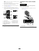
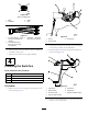
Connecting the Wires locknuts (M8), and 4 hex-head screws (M8 x 25 mm) as shown in Figure 12. 1. Connect a headlamp cable to the left headlamp by passing the end with just the pins through the hole in the headlamp body from the inside so that the connector is inside the lamp (Figure 14). Figure 12 1. Locknut (M8) 4. Hex-head screw (M8 x 25 mm) 2. Washer (M8) 5. Front light bracket assembly Figure 14 3. Washer (5/16 inch) 2. Connect the connector to the headlamp. 3.
Figure 16 View on cable entry 1. Black 2. Red/white 3. Green 4. Blue Figure 17 1. Front marker light — black wire (top), red/white wire (bottom) Figure 18 3. Headlamp — black wire (top), blue wire (bottom) 1. Screw 3. Control pod 2. Control panel 2. Front indicator light — black wire (top), green wire (bottom) 2. Carefully lift off the panel, ensuring that the connectors to the existing switches are not disturbed. 3. Feed the longest end of the connector lead down the control arm (Figure 19). 6.
5. On the rear face of the control pod, above the key switch, remove the switch blank panels between the auto limited lift and beacon switches (Figure 20). 5 Completing the Installation Parts needed for this procedure: 2 Adhesive reflector 20 Cable tie 1 Serial label Procedure 1. Cable tie all cables for the front lights, rear lights and the pressure switch so that they are secure and to prevent them from becoming trapped or chafed. 2. Connect the positive battery cable. Figure 20 1.
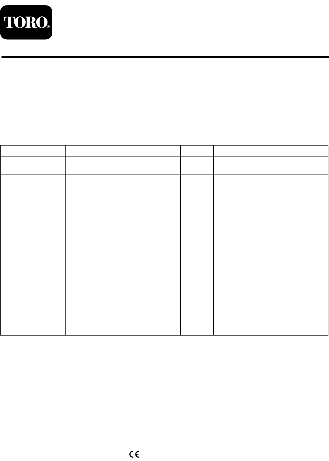
Brake Lights 8. Apply the serial label adjacent to the machine serial label. Operation The brake lights automatically turn on when the machine is decelerating (when the control pedal is returning to neutral, when travelling in a forward direction only). Position the marker lights (front and rear). Press the top of the switch—the switch will illuminate and the red (rear) and white (front) marker lights will turn on. Maintenance Replace all worn or damaged parts with genuine Toro parts.
Notes: 11
Notes: 12
Notes: 13
Declaration of Incorporation Model No. 02918 Serial No. Product Description Invoice Description General Description Directive 31600001 and Up Road Light Kit including Brake Lights KIT - ROAD LIGHTS W/ BRAKE LIGHTS Light Kit 2004/108/EC Relevant technical documentation has been compiled as required per Part B of Annex VII of 2006/42/EC. We will undertake to transmit, in response to requests by national authorities, relevant information on this partly completed machinery.
International Distributor List Distributor: Agrolanc Kft Asian American Industrial (AAI) B-Ray Corporation Brisa Goods LLC Casco Sales Company Ceres S.A. CSSC Turf Equipment (pvt) Ltd. Cyril Johnston & Co. Cyril Johnston & Co. Fat Dragon Femco S.A. FIVEMANS New-Tech Co., Ltd ForGarder OU G.Y.K. Company Ltd. Geomechaniki of Athens Golf international Turizm Hako Ground and Garden Hako Ground and Garden Hayter Limited (U.K.) Hydroturf Int. Co Dubai Hydroturf Egypt LLC Irrimac Irrigation Products Int'l Pvt Ltd.
The Toro Warranty A Limited Warranty Conditions and Products Covered The Toro® Company and its affiliate, Toro Warranty Company, pursuant to an agreement between them, jointly warrant your Toro Commercial product (“Product”) to be free from defects in materials or workmanship for two years or 1500 operational hours*, whichever occurs first. This warranty is applicable to all products with the exception of Aerators (refer to separate warranty statements for these products).