
Installation Instructions


g308240
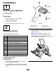
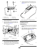
Figure6
1.Slope-sensordecal
InstallingtheKit
CT2240,LT3340,andLTFMachines
1.Removethe6screwssecuringthecontrolpanel
tothecontrolpod(Figure7).
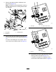
g304897
Figure7
1.Screw
3.Plug
2.Controlpanel4.Controlpod
2.Carefullyliftoffthepanel,ensuringthatthe
connectorstotheexistingswitchesarenot
disturbed.
3.Removetheplug(Figure7)fromtheconsole.
4.InserttheLEDlightintotheconsole.
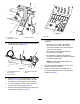
5.InstallthewireharnessasshowninFigure8.
6.ConnecttheLEDlighttothewire-harness
connectorlabeledP08(Figure8).
g304404
Figure8
1.Wireharness
5.Connector—P09
2.Connector—P086.Controlpod
3.LEDlight
7.Controlarm
4.Alarm8.Routethewireharness
towardtherollbar.
7.Connectthealarmtothewire-harnessconnector
labeledP09(Figure8).
8.Routetheremainingendofthewireharness
downthecontrolarm(Figure8).
9.Usethepreviously-removedscrewstosecure
thecontrolpaneltothecontrolpod.
10.Raisethehood.
11.Routethewireharnessalongthemachine
chassisanduptotheelectricalpanel.
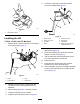
12.Use2bolts(M6x35mm)and2angenuts(M6)
tosecuretheslopesensortotheslope-sensor
mount(Figure9).
4