
Installation Instructions
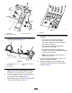


g304544
Figure9
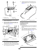
1.Bolt(M6x35mm)3.Slopesensor
2.Slopesensormount4.Flangenut(M6)
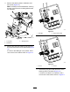
13.Connectthewire-harnessconnectorlabeled
P02totheslopesensor.
14.Use2bolts(M6x25mm)and2angenuts
(M6)tosecuretheslopesensormounttothe
electricalpanel(Figure10).
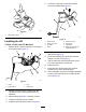
g304543
Figure10
1.Slopesensormount3.Bolt(M6x25mm)
2.Flangenut(M6)
15.Connectthekit-wire-harnessconnectorlabeled
P01tooneofthe6-pinsealedconnectors
locatedbelowtherelaysontheelectricalpanel.
16.Usecabletiestosecurethewireharnessaway
frommovingpartsorpinchpoints.
17.Installtheslope-sensordecaladjacenttothe
machine-stabilitydecalonthestorage-podlid
(Figure11).
g308336
Figure11
1.Machine-stabilitydecal
2.Slope-sensordecal
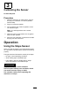
InstallingtheKit
PLH800Machines
1.Removethebatterycover;refertotheelectrical
systemmaintenancesectionofyourOperator’s
Manual.
2.Use2bolts(M6x35mm)and2angenuts
(M6)tosecuretheslopesensoronthemounting
plateinfrontofthebattery(Figure12).
g307264
Figure12
1.Battery
2.Slopesensor
5