
Installation Instructions

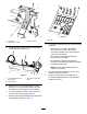


g305020
Figure3
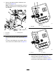
1.Bolt(M10)3.Flangenut(M10)
2.Slopesensormount
4.InstallthewireharnessconnectorlabeledP02
totheslopesensor(Figure4).
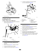
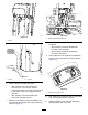
g307124
Figure4
1.Coilthewireharnessin
thislocation.
3.Wireharnessconnector
(P02)
2.Wireharness
5.Routethewireharnesstowardsthecontrol
panel(Figure4)andensurethatitissecured
andawayfrommovingpartsorpinchpoints.
6.Coilanyadditionalamountofwireharnessto
theleftofthecontrolpanel(Figure4).
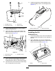
7.RemovetheplugandinstalltheLEDlightinthe
controlpanelasshowninFigure5.
g307377
Figure5
1.LEDlight
8.Connecttheremainingwire-harnessconnectors
asfollows:
•WireharnessconnectorlabeledP01:
Connecttooneofthe6-pinsealed
connectorslocatedonthemainharness
belowthecontrolpanel.
•WireharnessconnectorlabeledP08:
ConnecttotheLEDlight.
•WireharnessconnectorlabeledP09:
Connecttothealarmandpositionthealarm
underthecontrolpanel.
Note:Ensurethatthealarmdoesnot
obstructanycontrols.
9.Securetheoperator’splatform;refertoyour
machineOperator’sManual.
10.Installtheslope-sensordecaladjacentto
themachine-stabilitydecalontheoperator’s
platform(Figure6).
3