
Operator's Manual


g011213
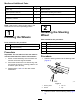
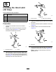
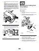
Figure5
1.Positive(+)batterycable2.Negative(–)batterycable
Important:Ifyoueverremovethebattery,
ensurethatthebatteryclampboltsare
installedwiththeboltheadspositionedon
thebottomsideandthenutsonthetopside.
Iftheclampboltsarereversed,theymay
interferewiththehydraulictubeswhenyou
shiftthecuttingunits.
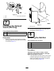
6.CoatbothbatteryconnectionswithGrafo112X
skin-overgrease(ToroPartNo.505-47)orlight
greasetopreventcorrosion.
7.Slidetherubberbootoverthepositiveterminal
topreventapossibleshortfromoccurring.
8.Installthebatterycover.
4
CheckingtheAngle
Indicator
Partsneededforthisprocedure:
1Inclinometer
Procedure
1.Parkthemachineonaat,levelsurface.
2.Verifythatthemachineislevelbyplacing
ahandheldinclinometer(suppliedwiththe
machine)ontheframecrossrail,bythefuel
tank(Figure6).Theinclinometershouldread
zerodegreeswhenviewedfromtheoperator’s
position.
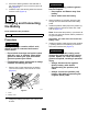
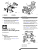
g008873
Figure6
1.Angleindicator
3.Iftheinclinometerdoesnotreadzerodegrees,
movethemachinetoalocationwhereazero
degreereadingisattained.Theangleindicator,
mountedonthemachine,shouldnowreadzero
degreesaswell.
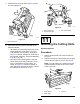
4.Iftheangleindicatordoesnotreadzerodegrees,
loosenthe2screwsandnutssecuringtheangle
indicatortothemountingbracket,adjustthe
indicatortoattainazerodegreereading,and
tightenthebolts.
5
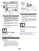
AdjustingTireAirPressure
NoPartsRequired
Procedure
Adjustthetireairpressureateachofthetires;referto
CheckingtheTirePressure(page45).
Note:Thetiresareover-inatedforshipping.
14