
Operator's Manual
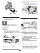


g008879
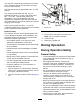
Figure28
1.Wearbar2.Bumperstrap
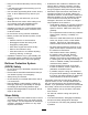
Iftheclearanceisnotinthisrange,adjustthe
rearcylinderasfollows:
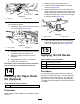
A.Lowerthecuttingunitsandbackoffthejam
nutonthecylinder(Figure29).
g008880
Figure29
1.Rearcylinder2.Adjustingnut
B.Graspthecylinderrodclosetothenutwith
apliersandragandrotatetherod.
C.Raisethecuttingunitsandcheckthe
clearance.
D.RepeatstepsAthroughCifnecessary.
E.Tightentheclevisjamnut.
Important:Lackofclearanceatthefrontstopsor
therearwearbarcoulddamagetheliftarms.
14
InstallingtheTipperRoller
Kit(Optional)
Partsneededforthisprocedure:
1
Tipperrollerkit(notincluded)
Procedure
Whencuttinginhigherheightsofcut,installtheTipper
RollerKit.
1.Raisethecuttingunitsallthewayup.
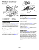
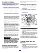
2.Locatetheframebracketabovethecenter
cuttingunit(Figure30).
3.Whilepressingdownonthefrontrollerofthe
centercuttingunit,determinewhichholesonthe
tipperbracketalignwiththeframebracketholes
toattainthesamerollercontactwhenthetipper
bracketisinstalled(Figure30).
g016925
Figure30
1.Framebracket2.Tipperbracket
4.Lowerthecuttingunitsandmountthetipper
brackettotheframewiththe2carriagebolts
and2nutssuppliedwiththekit(Figure30).
15
ApplyingtheCEDecals
Partsneededforthisprocedure:
1
Warningdecal(121-3598)
1
CEdecal
1Productionyeardecal
Procedure
OnmachinesrequiringCEcompliance,applythe
productionyeardecal(PartNo.133-5615)nearthe
serialplate,theCEdecal(PartNo.93-7252)near
thehoodlock,andtheCEwarningdecal(PartNo.
121-3598)overthestandardwarningdecal(PartNo.
121-3628).
22