Form No. 3393-332 Rev A 5, 8, and 11-Blade 27-inch and 8-Blade 32-inch DPA Cutting Unit Reelmaster® 3100-D Series Traction Unit Model No. Model No. Model No. Model No. Register at www.Toro.com. Original Instructions (EN) 03180—Serial No. 03181—Serial No. 03182—Serial No. 03183—Serial No.
This reel-blade lawnmower is mounted to a ride-on machine and is intended to be used by professional, hired operators in commercial applications. It is primarily designed for cutting grass on well-maintained lawns in parks, golf courses, sports fields, and on commercial grounds. It is not designed for cutting brush, mowing grass and other growth alongside highways, or for agricultural uses.
Safety Cutting Unit Accessories and Kits (see parts catalog for part numbers) ...................................... 9 Operation ....................................................................10 Adjustments ..........................................................10 Height-of-Cut Chart Terms .....................................11 Height-of-Cut Chart ...............................................12 Servicing the Bedknife ............................................16 Maintenance ....................
• Perform only those maintenance instructions described in replacement parts and accessories made by other manufacturers. Look for the Toro logo to assure genuineness. Using unapproved replacement parts and accessories could void the warranty of The Toro Company. this manual. If major repairs are ever needed or assistance is desired, contact an Authorized Toro Distributor. • To ensure optimum performance and safety, always purchase genuine Toro replacement parts and accessories to keep the Toro all Toro.
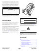
Setup Loose Parts Use the chart below to verify that all parts have been shipped. Procedure Description 1 2 3 4 5 Use Qty. Cutting unit 1 Inspect the cutting unit. No parts required – Use the cutting unit kickstand. No parts required – Adjust the rear shield. No parts required – Mounting the counter weights. Fixed plate kit (not included) 1 Install the Fixed Plate Kit (Optional). Media and Additional Parts Description Use Qty.
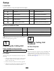
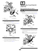
Figure 4 Figure 3 1. Rear shield 2. Cap screw 1. Cutting unit kickstand 4 3 Mounting the Counter Weights Adjusting the Rear Shield No Parts Required No Parts Required Procedure Procedure All cutting units are shipped with the counter weight mounted to the left end of the cutting unit. Use the following diagram to determine the position of the counter weights and reel motors. Under most conditions, the best dispersion is attained when the rear shield is closed (front discharge).
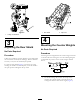
5 Installing the Fixed Plate Kit (Optional) Parts needed for this procedure: 1 Fixed plate kit (not included) Procedure 1. Remove the nuts and washers securing the lift links to the cutting unit side plate and carrier frame (Figure 9). Figure 6 3. Mounting bolts 1. O-ring 2. Counter weight 2. On right end of cutting unit, remove the plastic plug from the bearing housing (Figure 7). 3. Remove the 2 bolts from the right side plate (Figure 7). Figure 8 1. Nuts 2. Washers 2.
3. Loosen the locknuts securing the height-of-cut brackets to the cutting unit side plates (Figure 10). Figure 10 1. Height-of-cut bracket 3. Adjusting screw 2. Locknut 4. Remove the height-of-cut brackets and the roller from the cutting unit. 5. Repeat the procedure on the remaining cutting units.
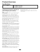
Product Overview Specifications Weight 27 27 27 32 inch 5 Blade – 67 kg (148 lb.) inch 8 Blade – 69 kg (153 lb.) inch 11 Blade – 72 kg (158 lb.) inch 8 Blade – 76 kg (167 lb.) Cutting Unit Accessories and Kits (see parts catalog for part numbers) Roller Rebuild Tool Kit: Includes all the tools and the installation instructions required to rebuild a roller with the roller rebuild kit. Note: All accessories and kits are 1 per cutting unit unless otherwise specified.
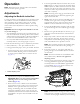
Operation 4. Turn the right bedbar adjuster clockwise until you feel light pressure (i.e. drag) on the shim, then back off the bedbar adjuster two clicks and remove the shim. (Since adjusting one side of the cutting unit affects the other side, the two clicks will provide clearance for when the other side is adjusted) Note: Determine the left and right sides of the machine from the normal operating position.
Adjusting the Rear Roller 1. Adjust the rear roller brackets (Figure 13) to the desired height of cut range by positioning the required amount of spacers below the side plate mounting flange (Figure 13) per the HOC Chart. g020698 Figure 14 1. Side plate mounting cap screws Figure 13 1. Spacer 3. Side plate mounting flange 2. Roller bracket Height-of-Cut Chart Terms 2. Raise rear of cutting unit and place a block under bedknife. Height-of-Cut Setting (HOC) 3.
setups cut more grass off by allowing the spinning reel to pull more grass up into the bedknife. Figure 15 1. Rear spacers 32 mm (1.250 inches) Less Normal More 4 5 6 35 mm (1.375 inches) Less Normal More 4 5 6 38 mm (1.500 inches) Less Normal More 5 6 7 41 mm (1.625 inches) Less Normal More 6 7 8 44 mm (1.750 inches) Less Normal More 6 7 8 48 mm (1.875 inches) Less Normal More 7 8 9 51 mm (2.000 inches) Less Normal More 7 8 9 54 mm (2.125 inches)* Less Normal More 8 9 10 57 mm (2.
Adjusting the Height of Cut 1. Loosen locknuts securing height-of-cut brackets to cutting unit side plates (Figure 16). Figure 18 Figure 16 1. Adjusting screw Important: When set properly, the rear and front rollers will contact the gauge bar and the screw will be snug against the bedknife. This ensures that the height-of-cut is identical at both ends of the bedknife. 3. Height-of-cut bracket 2. Locknut 2. Loosen nut on gauge bar (Figure 17) and set adjusting screw to desired height-of-cut.
Cutting Unit Characteristics The dual knob bedknife-to-reel adjustment system incorporated in this cutting unit simplifies the adjustment procedure needed to deliver optimum mowing performance. The precise adjustment possible with the dual knob/bedbar design gives the necessary control to provide a continual self-sharpening action-thus maintaining sharp cutting edges, ensuring good quality-of-cut, and greatly reducing the need for routine back lapping. Figure 19 1. Bedknife Lip Height * 6.
Figure 21 1. Lead-in chamfer on right end of bedknife 2. 1.5 mm (.060 inch) 3. 8.6 mm (.340 inch) Note: Do not make lead-in chamfer too large as it may cause turf tufting.
Servicing the Bedknife The bedknife service limits are listed in the following charts. Important: Operating the cutting unit with the bedknife below the “service limit” may result in poor after-cut appearance and reduce the structural integrity of the bedknife for impacts. Bedknife Service Limit Chart Bedknife Part No. Bedknife Lip Height * Service Limit* Low HOC (Optional) 120–1641 (27 inch) 120–1642 (32 inch) 5.6 mm (.220 inch) .190 inch (4.
Maintenance 2. Using a rag or thickly padded glove, hold on to the reel blade and try to move the reel assembly side to side (Figure 26). Lubrication Each cutting unit has (6) grease fittings (Figure 24) that must be lubricated regularly with No. 2 General Purpose Lithium Base Grease. The lubrication points are front roller (2), rear roller (2) and reel bearing (2). Note: Lubricating cutting units immediately after washing helps purge water out of bearings and increases bearing life. 1.
Servicing the Bedbar Removing the Bedbar 1. Turn bedbar adjuster screws, counterclockwise, to back bedknife away from reel (Figure 28). Figure 30 1. Bedbar bolt 2. Nut Assembling the Bedbar 1. Install bedbar, positioning mounting ears between washer and bedbar adjuster. 2. Secure bedbar to each side plate with bedbar bolts (nuts on bolts) and 6 washers. A nylon washer is to be positioned on each side of side plate boss. Place a steel washer outside each of the nylon washers (Figure 30).
Servicing the HD Dual Point Adjusters (DPA) 4. Install a wave washer onto the adjuster shaft and slide the adjuster shaft into the flange bushings in the cutting unit frame (Figure 32). 1. Remove all parts (refer to Installation Instructions for HD DPA Kit Model No. 120–7230 and to Figure 32). 5. Secure the adjuster shaft with a flat washer and lock nut (Figure 32). Torque the lock nut to 20 to 27 N-m (15 to 20 ft-lb). 2.
Servicing the Roller bearings, bearing nuts, inner seals and outer seals to rebuild a roller. The Roller Rebuild Tool Kit includes all the tools and the installation instructions required to rebuild a roller with the roller rebuild kit. Refer to your parts catalog or contact your distributor for assistance. A Roller Rebuild Kit, Part No. 114–5430 and a Roller Rebuild Tool Kit, Part No. 115–0803 (Figure 33) are available for servicing the roller. The Roller Rebuild Kit includes all the Figure 33 1.
Notes: 21
Declaration of Incorporation The Toro Company, 8111 Lyndale Ave. South, Bloomington, MN, USA declares that the following unit(s) conform(s) to the directives listed, when installed in accordance with the accompanying instructions onto certain Toro models as indicated on the relevant Declarations of Conformity. Model No. Serial No.
International Distributor List Distributor: Country: Phone Number: Distributor: Phone Number: 57 1 236 4079 Colombia Japan 81 3 3252 2285 Czech Republic 420 255 704 220 420 255 704 Slovakia 220 Argentina 54 11 4 821 9999 Russia 7 495 411 61 20 Ecuador 593 4 239 6970 Finland 358 987 00733 Agrolanc Kft Balama Prima Engineering Equip. B-Ray Corporation Hungary Hong Kong Korea 36 27 539 640 852 2155 2163 82 32 551 2076 Maquiver S.A. Maruyama Mfg. Co. Inc. Mountfield a.s.
Toro General Commercial Product Warranty A Two-Year Limited Warranty Conditions and Products Covered The Toro Company and its affiliate, Toro Warranty Company, pursuant to an agreement between them, jointly warrant your Toro Commercial product (“Product”) to be free from defects in materials or workmanship for two years or 1500 operational hours*, whichever occurs first. This warranty is applicable to all products with the exception of Aerators (refer to separate warranty statements for these products).