
Operator's Manual
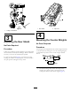
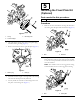
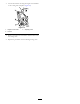
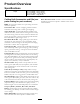
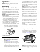

Figure6
1.O-ring
3.Mountingbolts
2.Counterweight
2.Onrightendofcuttingunit,removetheplasticplug
fromthebearinghousing(Figure7).
3.Removethe2boltsfromtherightsideplate(Figure7).
G003321
1
2
Figure7
1.Plasticplug
2.Bolts(2)
4.Installthecounterweighttotherightendofthecutting
unitwiththe2boltspreviouslyremoved.
5.Looselyinstallthe2reel-motormountingboltstothe
leftplateofthecuttingunit(Figure7).
5
InstallingtheFixedPlateKit
(Optional)
Partsneededforthisprocedure:
1
Fixedplatekit(notincluded)
Procedure
1.Removethenutsandwasherssecuringtheliftlinksto
thecuttingunitsideplateandcarrierframe(Figure9).
Figure8
1.Nuts2.Washers
2.Usingthenumber2holes,insertaxedplateontothe
boltsandsecurewiththenutsremoved.Thenumber
1holesaretobepositionedtowardthefront.Donot
reusethewashers.
Note:Thenumber1holeisalessaggressivesetting
andthenumber3holeisamoreaggressivesetting.
Figure9
1.Nuts2.Fixedplate
7