Form No. 3370-613 Rev D 5, 8 and 11-Blade 27-inch and 8-Blade 32–inch DPA Cutting Unit Reelmaster® 3100-D Series Traction Unit Model No. Model No. Model No. Model No. Register at www.Toro.com. Original Instructions (EN) 03180—Serial No. 03181—Serial No. 03182—Serial No. 03183—Serial No.
Model No. Serial No. Introduction This manual identifies potential hazards and has safety messages identified by the safety alert symbol (Figure 2), which signals a hazard that may cause serious injury or death if you do not follow the recommended precautions. This product complies with all relevant European directives, for details please see the separate product specific Declaration of Conformity (DOC) sheet.
Safety in moving parts. Always wear long pants and substantial shoes. Wearing safety glasses, safety shoes and a helmet is advisable and required by some local ordinances and insurance regulations. Hazard control and accident prevention are dependent upon the awareness, concern, and proper training of the personnel involved in the operation, transport, maintenance, and storage of the machine. Improper use or maintenance of the machine can result in injury or death.
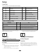
Setup Loose Parts Use the chart below to verify that all parts have been shipped. Procedure Description 1 2 3 4 5 6 Use Qty.
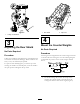
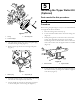
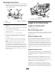
Figure 4 Figure 3 1. Rear shield 2. Cap screw 1. Cutting unit kickstand 4 3 Mount the Counter Weights Adjusting the Rear Shield No Parts Required No Parts Required Procedure Procedure All cutting units are shipped with the counter weight mounted to the left end of the cutting unit. Use the following diagram to determine the position of the counter weights and reel motors. Under most conditions, best dispersion is attained when the rear shield is closed (front discharge).
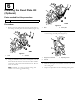
5 Installing the Tipper Roller Kit (Optional) Parts needed for this procedure: 1 Tipper roller kit (not included) Procedure When cutting in higher heights of cut, it is recommended that the Tipper Roller Kit be installed. 1. Raise the cutting units all the way up. Figure 6 2. Locate the frame bracket above the center cutting unit (Figure 8). 3. Mounting bolts 1. O-ring 3.
6 Installing the Fixed Plate Kit (Optional) Parts needed for this procedure: 1 Fixed plate kit (not included) Procedure Figure 10 1. Remove the nuts and washers securing the lift links to the cutting unit side plate and carrier frame (Figure 10). 1. Nuts 2. Fixed plate 3. Loosen the locknuts securing the height-of-cut brackets to the cutting unit side plates (Figure 11). Figure 9 1. Nuts Figure 11 2. Washers 1. Height-of-cut bracket 3. Adjusting screw 2. Locknut 2.
Product Overview Specifications Weight 27 27 27 32 inch 5 Blade – 67 kg (148 lb.) inch 8 Blade – 69 kg (153 lb.) inch 11 Blade – 72 kg (158 lb.) inch 8 Blade – 76 kg (167 lb.) Cutting Unit Accessories and Kits (see parts catalog for part numbers) Roller Rebuild Tool Kit: Includes all the tools and the installation instructions required to rebuild a roller with the roller rebuild kit. Note: All accessories and kits are 1 per cutting unit unless otherwise specified.
Operation 4. Turn the right bedbar adjuster clockwise until you feel light pressure (i.e. drag) on the shim, then back off the bedbar adjuster two clicks and remove the shim. (Since adjusting one side of the cutting unit affects the other side, the two clicks will provide clearance for when the other side is adjusted) Note: Determine the left and right sides of the machine from the normal operating position.
Adjusting the Rear Roller 1. Adjust the rear roller brackets (Figure 14) to the desired height of cut range by positioning the required amount of spacers below the side plate mounting flange (Figure 14) per the HOC Chart. g020698 Figure 15 1. Side plate mounting cap screws Figure 14 1. Spacer 3. Side plate mounting flange 2. Roller bracket Height of Cut Chart Terms 2. Raise rear of cutting unit and place a block under bedknife. Height of Cut Setting (HOC) 3.
setups cut more grass off by allowing the spinning reel to pull more grass up into the bedknife. Figure 16 1. Rear spacers 32 mm (1.250 inches) Less Normal More 4 5 6 35 mm (1.375 inches) Less Normal More 4 5 6 38 mm (1.500 inches) Less Normal More 5 6 7 41 mm (1.625 inches) Less Normal More 6 7 8 44 mm (1.750 inches) Less Normal More 6 7 8 48 mm (1.875 inches) Less Normal More 7 8 9 51 mm (2.000 inches) Less Normal More 7 8 9 54 mm (2.125 inches)* Less Normal More 8 9 10 57 mm (2.
Adjusting the Height of Cut 1. Loosen locknuts securing height-of-cut brackets to cutting unit side plates (Figure 17). Figure 19 Figure 17 1. Adjusting screw Important: When set properly, the rear and front rollers will contact the gauge bar and the screw will be snug against the bedknife. This ensures that the height-of-cut is identical at both ends of the bedknife. 3. Height-of-cut bracket 2. Locknut 2. Loosen nut on gauge bar (Figure 18) and set adjusting screw to desired height-of-cut.
Cutting Unit Characteristics The dual knob bedknife-to-reel adjustment system incorporated in this cutting unit simplifies the adjustment procedure needed to deliver optimum mowing performance. The precise adjustment possible with the dual knob/bedbar design gives the necessary control to provide a continual self-sharpening action-thus maintaining sharp cutting edges, ensuring good quality-of-cut, and greatly reducing the need for routine back lapping. Figure 20 1. Bedknife Lip Height * 6.
Figure 22 1. Lead-in chamfer on right end of bedknife 2. 1.5 mm (.060 inch) 3. 8.6 mm (.340 inch) Note: Do not make lead-in chamfer too large as it may cause turf tufting.
Servicing Bedknife The bedknife service limits are listed in the following charts. Important: Operating the cutting unit with the bedknife below the “service limit” may result in poor after-cut appearance and reduce the structural integrity of the bedknife for impacts. Bedknife Service Limit Chart Bedknife Part No. Bedknife Lip Height * Service Limit* Low HOC (Optional) 120–1641 (27 inch) 120–1642 (32 inch) 5.6 mm (.220 inch) .190 inch (4.
Maintenance 2. Using a rag or thickly padded glove, hold on to the reel blade and try to move the reel assembly side to side (Figure 27). Lubrication Each cutting unit has (6) grease fittings (Figure 25) that must be lubricated regularly with No. 2 General Purpose Lithium Base Grease. The lubrication points are front roller (2), rear roller (2) and reel bearing (2). Note: Lubricating cutting units immediately after washing helps purge water out of bearings and increases bearing life. 1.
Servicing the Bedbar Removing the Bedbar 1. Turn bedbar adjuster screws, counterclockwise, to back bedknife away from reel (Figure 29). Figure 31 1. Bedbar bolt 2. Nut Assembling the Bedbar 1. Install bedbar, positioning mounting ears between washer and bedbar adjuster. 2. Secure bedbar to each side plate with bedbar bolts (nuts on bolts) and 6 washers. A nylon washer is to be positioned on each side of side plate boss. Place a steel washer outside each of the nylon washers (Figure 31).
Servicing the HD Dual Point Adjusters (DPA) 4. Install a wave washer onto the adjuster shaft and slide the adjuster shaft into the flange bushings in the cutting unit frame (Figure 33). 1. Remove all parts (refer to Installation Instructions for HD DPA Kit Model No. 120–7230 and to Figure 33). 5. Secure the adjuster shaft with a flat washer and lock nut (Figure 33). Torque the lock nut to 20 to 27 N-m (15 to 20 ft-lb). 2.
Servicing the Roller bearings, bearing nuts, inner seals and outer seals to rebuild a roller. The Roller Rebuild Tool Kit includes all the tools and the installation instructions required to rebuild a roller with the roller rebuild kit. Refer to your parts catalog or contact your distributor for assistance. A Roller Rebuild Kit, Part No. 114–5430 and a Roller Rebuild Tool Kit, Part No. 115–0803 (Figure 34) are available for servicing the roller. The Roller Rebuild Kit includes all the Figure 34 1.
Notes: 20
Notes: 21
Notes: 22
Declaration of Incorporation The Toro Company, 8111 Lyndale Ave. South, Bloomington, MN, USA declares that the following unit(s) conform(s) to the directives listed, when installed in accordance with the accompanying instructions onto certain Toro models as indicated on the relevant Declarations of Conformity. Model No. Serial No.
The Toro Total Coverage Guarantee A Limited Warranty Conditions and Products Covered The Toro Company and its affiliate, Toro Warranty Company, pursuant to an agreement between them, jointly warrant your Toro Commercial product (“Product”) to be free from defects in materials or workmanship for two years or 1500 operational hours*, whichever occurs first. This warranty is applicable to all products with the exception of Aerators (refer to separate warranty statements for these products).