
Operator's Manual
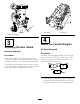

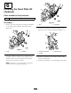


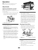

Figure6
1.O-ring
3.Mountingbolts
2.Counterweight
2.Onrightendofcuttingunit,removetheplasticplug
fromthebearinghousing(Figure7).
3.Removethe2capscrewsfromtherightsideplate
(Figure7).
G003321
1
2
Figure7
1.Plasticplug
2.Capscrew(2)
4.Installthecounterweighttotherightendofthe
cuttingunitwiththe2screwspreviouslyremoved.
5.Looselyinstallthe2reelmotormountingcapscrews
totheleftsideplateofthecuttingunit(Figure7).
5
InstallingtheTipperRollerKit
(Optional)
Partsneededforthisprocedure:
1
Tipperrollerkit(notincluded)
Procedure
Whencuttinginhigherheightsofcut,itisrecommended
thattheTipperRollerKitbeinstalled.
1.Raisethecuttingunitsallthewayup.
2.Locatetheframebracketabovethecentercutting
unit(Figure8).
3.Whilepressingdownonthefrontrollerofthecenter
cuttingunit,determinewhichholesonthetipper
bracketalignwiththeframebracketholestoattain
thesamerollercontactwhenthetipperbracketis
installed(
Figure8).
Figure8
1.Framebracket2.Tipperbracket
4.Lowerthecuttingunitsandmountthetipperbracket
totheframewiththe(2)carriageboltsandnuts
suppliedwiththekit(Figure8).
6