Form No. 3363-326 Rev A 5, 8, and 11 Blade DPA Cutting Units Reelmaster® 3100 Traction Units Model No. 03180—Serial No. 310000001 and Up Model No. 03181—Serial No. 310000001 and Up Model No. 03183—Serial No. 310000001 and Up Model No. 03182—Serial No. 310000001 and Up To register your product or download an Operator's Manual or Parts Catalog at no charge, go to www.Toro.com.
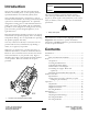
Model No. Introduction Serial No. This product complies with all relevant European directives, for details please see the separate product specific Declaration of Conformity (DOC) sheet. This manual identifies potential hazards and has safety messages identified by the safety alert symbol (Figure 2), which signals a hazard that may cause serious injury or death if you do not follow the recommended precautions.
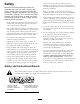
Safety Always wear long pants and substantial shoes. Wearing safety glasses, safety shoes and a helmet is advisable and required by some local ordinances and insurance regulations. Hazard control and accident prevention are dependent upon the awareness, concern, and proper training of the personnel involved in the operation, transport, maintenance, and storage of the machine. Improper use or maintenance of the machine can result in injury or death.
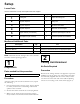
Setup Loose Parts Use the chart below to verify that all parts have been shipped. Procedure Description 1 2 3 4 5 6 Use Qty.
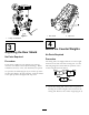
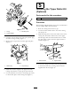
Figure 4 1. Rear shield Figure 3 2. Cap screw 1. Cutting unit kickstand 4 3 Mount the Counter Weights Adjusting the Rear Shield No Parts Required No Parts Required Procedure Procedure All cutting units are shipped with the counter weight mounted to the left end of the cutting unit. Use the following diagram to determine the position of the counter weights and reel motors. Under most conditions, best dispersion is attained when the rear shield is closed (front discharge).
5 Installing the Tipper Roller Kit (Optional) Parts needed for this procedure: 1 Tipper roller kit (not included) Procedure When cutting in higher heights of cut, it is recommended that the Tipper Roller Kit be installed. 1. Raise the cutting units all the way up. Figure 6 2. Locate the frame bracket above the center cutting unit (Figure 8). 3. Mounting bolts 1. O-ring 2. Counter weight 3.
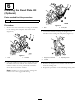
6 Installing the Fixed Plate Kit (Optional) Parts needed for this procedure: 1 Fixed plate kit (not included) Procedure Figure 10 1. Nuts 1. Remove the nuts and washers securing the lift links to the cutting unit side plate and carrier frame (Figure 10). 3. Loosen the locknuts securing the height-of-cut brackets to the cutting unit side plates (Figure 11). Figure 11 Figure 9 1. Nuts 2. Fixed plate 1. Height-of-cut bracket 2. Locknut 2. Washers 2.
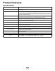
Product Overview Specifications Tractors Height of Cut These cutting units will mount on the Reelmaster 3100 Traction Unit. Cutting height is adjusted on the front roller by two vertical screws and held by two locking cap screws Height Of Cut Range Standard bench height of cut range is .250 inch (3 mm) to 1.00 inch (25 mm). Bench height of cut range with the High Height of Cut Kit installed is 1.00 inch (25 mm) to 2.00 inches (51 mm). Bench height of cut range with the Fixed Plate Kit installed is 2.
Cutting Unit Accessories and Kits (see parts catalog for part numbers) Roller Rebuild Kit: Includes all the bearings, bearing nuts, inner seals and outer seals required to rebuild a roller. Roller Rebuild Tool Kit: Includes all the tools and the installation instructions required to rebuild a roller with the roller rebuild kit. Note: All accessories and kits are 1 per cutting unit unless otherwise specified.
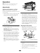
Operation Note: Determine the left and right sides of the machine from the normal operating position. Adjustments Adjusting the Bedknife to the Reel G003323 Bedknife to reel adjustment is accomplished by loosening or tightening bedbar adjusting screws, located on top of mower. Figure 13 4. Check for light contact at other end of reel using paper and adjust as required. 5.
Paspalum, Zoysia) while cool season grasses (Bent, Bluegrass, Rye) may require normal to more aggressive setups. More aggressive setups cut more grass off by allowing the spinning reel to pull more grass up into the bedknife. 6. Re-secure roller bracket and spacers to underside of side plate mounting flanges with nuts previously removed. 7. Verify that bedknife to reel contact is correct. Tip mower to expose front and rear rollers and bedknife.
Height of Cut Chart Less Normal More 2.500" (64 mm)** 9 10 11 HOC Setting Aggressiveness of Cut No. of Rear Spacers 0.250" (6 mm) Less Normal More 0 0 1 * High HOC Kit (Part No. 110-9600) must be installed. Front HOC bracket must be positioned in the top side plate hole. ** Fixed Plate Kits (Part No. 119–0646–03) are recommended for 2.00 to 2.5 inch (51 to 64 mm) heights of cut. 0.375" (9 mm) Less Normal More 0 1 2 Adjusting the Height of Cut 0.500" (13 mm) Less Normal More 0 1 2 0.
4. Rotate the adjusting screw until the front roller contacts the gauge bar (Figure 19). Adjust both ends of roller until entire roller is parallel to the bedknife. Figure 20 1. Bedknife Lip Height * 6. To adjust the height of cut when fixed plate kits are installed on the cutting units, proceed as follows: • Remove the height of cut brackets and front roller as described in Procedure 6 in the Set-Up section.
Cutting Unit Characteristics Note: Over time, the chamfer (Figure 22) will need to be reground as it is only designed to last 40% of the bedknife life. The dual knob bedknife-to-reel adjustment system incorporated in this cutting unit simplifies the adjustment procedure needed to deliver optimum mowing performance.
Figure 23 1.
Maintenance Lubrication Each cutting unit has (6) grease fittings (Figure 25) that must be lubricated regularly with No. 2 General Purpose Lithium Base Grease. Figure 26 The lubrication points are front roller (2), rear roller (2) and reel bearing (2). 1. Bedknife adjusting knob Note: Lubricating cutting units immediately after washing helps purge water out of bearings and increases bearing life. 2.
Note: Reel bearings do not require preload. Over tightening reel bearing adjuster nut will damage reel bearings. 4. Retighten set screw securing bearing adjusting nut to bearing housing. Torque to 12-15 in-lb. Servicing the Bedbar Removing the Bedbar 1. Turn bedbar adjuster screws, counterclockwise, to back bedknife away from reel (Figure 29). Figure 31 1. Bedbar bolt 2. Nut 3. Steel washer 4. Nylon washer Assembling the Bedbar 1.
Servicing the Roller outer seals to rebuild a roller. The Roller Rebuild Tool Kit includes all the tools and the installation instructions required to rebuild a roller with the roller rebuild kit. Refer to your parts catalog or contact your distributor for assistance. A Roller Rebuild Kit, Part No. 114–5430 and a Roller Rebuild Tool Kit, Part No. 115–0803 (Figure 33) are available for servicing the roller. The Roller Rebuild Kit includes all the bearings, bearing nuts, inner seals and Figure 33 1. 2. 3.
Notes: 19
The Toro Total Coverage Guarantee A Limited Warranty Conditions and Products Covered The Toro® Company and its affiliate, Toro Warranty Company, pursuant to an agreement between them, jointly warrant your Toro Commercial product (“Product”) to be free from defects in materials or workmanship for two years or 1500 operational hours*, whichever occurs first. This warranty is applicable to all products with the exception of Aerators (refer to separate warranty statements for these products).