
Installation Instructions
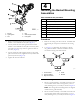
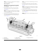
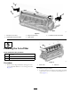
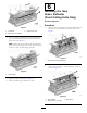
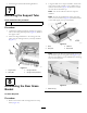
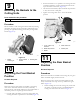
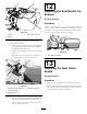
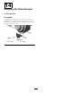
Table Of Contents
- .
- 1 Preparing the Machine
- 2 Mounting the Roller Bumper
- 3 Mounting the Hydro Guard
- 4 Installing the Basket Mounting Assemblies
- 5 Installing the Cut-off Bar
- 6 Installing the New Grass Deflector(Front Cutting Units Only)
- 7 Removing the Support Tube
- 8 Assembling the Rear Grass Basket
- 9 Mounting the Baskets to the Cutting Units
- 10 Adjusting the Front Basket Position
- 11 Adjusting the Rear Basket Position
- 12 Adjusting the Rear Basket Lip Bracket
- 13 Adjusting the Rear Grass Shield
- 14 Adjusting the Roller Bumper

g026365
Figure2
1.Bolt(2)
4.Bolt
2.Hydroguard
5.Cablesupportbracket
3.Nut6.Pumpplate
2.Removeandretainthe(2)boltssecuringtheneutral
brackettotheundersideofthehydro(Figure2).
3.Looselyattachthenewhydroguardandtheneutral
brackettotheundersideofthehydrowiththe(2)bolts
removedinthepriorstep.Donottightentheboltsat
thistime(Figure2).
4.Looselyattachthecablesupportbrackettothepump
platewiththenewbolt(suppliedinthekit)andthenut
previouslyremoved(Figure2).
5.Tightenalltheboltsandnuts.
4
InstallingtheBasketMounting
Assemblies
Partsneededforthisprocedure:
2
Guideassembly
2Bracketassembly
4
Carriagebolt(5/16x1inch)
4
Flangenut(5/16inch)
1
Basketbracketwithguideassembly(right)
1
Basketbracketwithbracketassembly(left)
2
Bolt(5/16x2-1/4inch)
2
Flangenut(5/16inch)
Procedure
1.Removethecuttingunitsfromcartons.Assembleand
adjustthempertheOperator'sManualforthecutting
unit.
2.UseFigure3todeterminethelocationsatwhich
theguideassembliesorbracketassembliesmustbe
mountedtocuttingunitcarrierframes.
g195013
Figure3
1.Centerbasket4.Guide
2.Leftfrontbasket
5.Bracket
3.Rightfrontbasket
FrontCuttingUnits
3.Mountaguideassemblytotheinsideoftherightend
ofeachcarrierframewith2carriagebolts(5/16x1
inch)andangenuts(5/16inch)asshowninFigure4.
Note:Thecarriageboltsandangeboltsareshipped
installedontheguideassembly.
4.Mountabracketassemblytotheinsideoftheleftend
ofeachcarrierframewith2carriagebolts(5/16x1
inch)andangenuts(5/16inch)asshowninFigure4.
3