
Installation Instructions
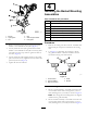
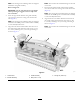
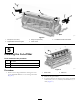
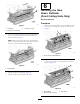
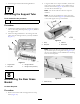
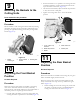
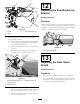
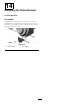
Table Of Contents
- .
- 1 Preparing the Machine
- 2 Mounting the Roller Bumper
- 3 Mounting the Hydro Guard
- 4 Installing the Basket Mounting Assemblies
- 5 Installing the Cut-off Bar
- 6 Installing the New Grass Deflector(Front Cutting Units Only)
- 7 Removing the Support Tube
- 8 Assembling the Rear Grass Basket
- 9 Mounting the Baskets to the Cutting Units
- 10 Adjusting the Front Basket Position
- 11 Adjusting the Rear Basket Position
- 12 Adjusting the Rear Basket Lip Bracket
- 13 Adjusting the Rear Grass Shield
- 14 Adjusting the Roller Bumper

g012219
Figure7
1.Cut-offbar3.Locknut(1/4inch)
2.Bolt(1/4x1-3/4inches)
4.Inserta1.5mm(0.060inch)feelergaugebetweenthe
topofthereelandthebottomofthecut-offbarto
checkclearance(Figure8).
Note:Makesurethebarandreelareequaldistance
apartacrossthefulllengthofthereel.Thecut-offbar
mustnotcontactthereelduringoperation.
g012220
Figure8
1.Feelergauge
5.Tightentheboltsandlocknuts(Figure7).
6.Donotinstallthegrassshieldatthistime.
6
InstallingtheNew
GrassDeector
(FrontCuttingUnitsOnly)
NoPartsRequired
Procedure
1.Removethe2centerdeectorsandthedeectorfrom
eachendoftheshield,leavingonlythe2shownin
Figure9.
g012221
Figure9
1.Donotremovethesedeectors.
2.Mountthenewdeectortotheleftendoftheshield
with2screws(10-24x1/2inch)andnuts(10-24)as
showninFigure10.
g012277
Figure10
1.Newdeector3.Nut(10-24)
2.Screw(10-24x1/2inch)
6