
Installation Instructions
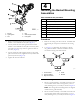
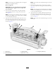
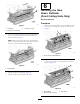
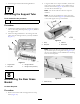
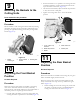
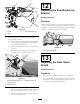
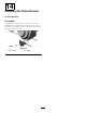
Table Of Contents
- .
- 1 Preparing the Machine
- 2 Mounting the Roller Bumper
- 3 Mounting the Hydro Guard
- 4 Installing the Basket Mounting Assemblies
- 5 Installing the Cut-off Bar
- 6 Installing the New Grass Deflector(Front Cutting Units Only)
- 7 Removing the Support Tube
- 8 Assembling the Rear Grass Basket
- 9 Mounting the Baskets to the Cutting Units
- 10 Adjusting the Front Basket Position
- 11 Adjusting the Rear Basket Position
- 12 Adjusting the Rear Basket Lip Bracket
- 13 Adjusting the Rear Grass Shield
- 14 Adjusting the Roller Bumper

3.Installthegrassshieldandremainingdeectors.
7
RemovingtheSupportTube
Partsneededforthisprocedure:
2
Flangelocknut(3/8inch)
Procedure
1.Unthreadthe2ange-headboltssecuringthesupport
tubetothecuttingunitsideplates(Figure11).Remove
thesupporttube.
2.Securetheange-headboltstothecuttingunitside
plateswiththe2angelocknuts(3/8inch)included
(Figure11).
g012222
Figure11
1.Supporttube
3.Flange-headbolt
2.Sideplate4.Flangelocknut(3/8inch)
8
AssemblingtheRearGrass
Basket
NoPartsRequired
Procedure
1.Removethewashersandnutsshippedonthestrap
bolts(Figure12).
2.Usingthecabletiesonstrapsashandles,stretcheach
strapuntilitcanbesecuredtotopofbasketwith2
washersandalocknut(Figure12).Positionawasher
oneachsideofthebaskettop.
Note:Cutoffthecabletiesafterthestrapsare
installed.
Note:Toeasetheinstallationofstraps,placean8
inchx4inchwoodblock(Figure12)insidethebasket
toraiseandsupportthetopofthebasket.
g012223
Figure12
1.Strap3.Cabletie
2.Strapbolt
4.Woodblock
Note:Ifthestrapsbecomestretchedanddonothold
topofbasketopen,usetheguideholes(Figure13)in
therearofthebaskettolocateanddrillnewmounting
holesforthestrapbolts.
g012224
Figure13
1.Guidehole(2)
7