
Operator's Manual
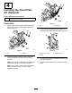
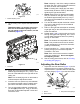

2.Raisetherearofthecuttingunitandplacea
blockunderthebedknife.
3.Removethe2nutssecuringeachrollerbracket
andspacertoeachside-platemountingange.
4.Lowertherollerandscrewsfromtheside-plate
mountingangesandspacers.
5.Placethespacersontothescrewsontheroller
brackets.
6.Securetherollerbracketandspacersto
undersideofsideplatemountingangeswith
thenutspreviouslyremoved.
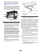
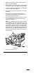
7.Verifythatthebedknife-to-reelcontactiscorrect.
Tipthemowertoexposethefrontandrear
rollersandbedknife.
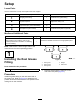
Note:Thepositionoftherearrollertothereel
iscontrolledbythemachiningtolerancesofthe
assembledcomponents;therefore,parallelingis
notrequired.Alimitedamountofadjustmentis
possiblebysettingthecuttingunitonasurface
plateandlooseningtheside-platemountingcap
screws(Figure15).Adjustandtightenthecap
screws.T orquethecapscrewsto37to45N·m
(27to33ft-lb).
g020698
Figure15
1.Side-platemountingcapscrews
10