Form No. 3407-779 Rev A 5, 8, and 11-Blade 27-inch and 8-Blade 32-inch DPA Edge Series Cutting Unit Reelmaster® 3100-D Series Traction Unit Model No. Model No. Model No. Model No. Register at www.Toro.com. Original Instructions (EN) 03188—Serial No. 03189—Serial No. 03190—Serial No. 03191—Serial No.
which signals a hazard that may cause serious injury or death if you do not follow the recommended precautions. WARNING CALIFORNIA Proposition 65 Warning This product contains a chemical or chemicals known to the State of California to cause cancer, birth defects, or reproductive harm. g000502 Figure 2 1. Safety-alert symbol This product complies with all relevant European directives. For details, please see the Declaration of Incorporation (DOI) at the back of this publication.
Safety advisable and required by some local ordinances and insurance regulations. Secure loose clothing. This machine has been designed in accordance with EN ISO 5395:2013 and ANSI B71.4-2012. • Tie back long hair. Do not wear jewelry. • Remove all debris or other objects that might be picked Improper use or maintenance of this equipment can result in injury or death. To reduce the potential for injury or death, comply with the following safety instructions.
Setup Loose Parts Use the chart below to verify that all parts have been shipped. Procedure Description 1 2 3 4 5 Use Qty. Cutting unit 1 Inspect the cutting unit. No parts required – Use the kickstand when tipping the cutting unit. No parts required – Adjust the rear shield. Straight grease fitting O-ring 1 1 Install the loose parts. Fixed plate kit (not included) 1 Install the fixed plate kit (optional). Media and Additional Parts Description Use Qty.
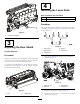
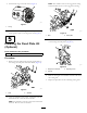
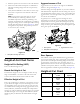
4 Installing the Loose Parts Parts needed for this procedure: 1 Straight grease fitting 1 O-ring Procedure The grease fitting must be installed on the reel-motor side of the cutting unit. Refer to Figure 5 to determine the position of the reel motors. g191340 Figure 3 1. Cutting-unit kickstand 3 g034633 Figure 5 Adjusting the Rear Shield No Parts Required 1. Cutting unit 1 4. Weight 2. Cutting unit 2 5. Reel motor 3. Cutting unit 3 Procedure 1.
Note: The number 1 hole is a less aggressive setting and the number 3 hole is a more aggressive setting. 4. Install the O-ring on the reel motor (Figure 7). g191072 Figure 7 1. O-ring 5. Install the reel motor, and grease the side plate until excess grease comes out of the grease vent (Figure 6). g011963 Figure 9 1. Nuts 5 2. Fixed plate 3. Loosen the locknuts securing the height-of-cut brackets to the cutting-unit side plates (Figure 10).
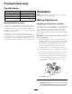
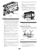
Product Overview Specifications Operation Weight Cutting Unit 27 inch, 5 blade 57 kg (125 lb) 27 inch, 8 blade 60 kg (132 lb) 27 inch, 11 blade 62 kg (136 lb) 32 inch, 8 blade 67 kg (147 lb) Note: Determine the left and right sides of the machine from the normal operating position. Making Adjustments Attachments/Accessories Adjusting the Bedknife to the Reel A selection of Toro-approved attachments and accessories is available for use with the machine to enhance and expand its capabilities.
9. From this position (i.e., 1 click in and shim not passing through) turn the bedbar adjusters clockwise 1 click each. Note: Each click turned moves the bedknife 0.022 mm (0.0009 inches). Do not overtighten the adjusting screws. 10. Test the cutting performance by inserting a long strip of cutting performance paper (Toro Part No. 125-5610) between reel and bedknife, perpendicular to the bedknife (Figure 13). Slowly rotate the reel forward; it should cut the paper. g191340 Figure 12 1.
Aggressiveness of Cut 5. Place the spacers onto the screws on the roller brackets. 6. Secure the roller bracket and spacers to underside of side plate mounting flanges with the nuts previously removed. 7. Verify that the bedknife-to-reel contact is correct. Tip the mower to expose the front and rear rollers and bedknife. Aggressiveness of cut refers to the angle of the bedknife relative to the ground (Figure 16). The best cutting-unit setup depends on your turf conditions and desired results.
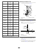
Less Normal More 2 3 4 22 mm (0.875 inch) Less Normal More 2 3 4 25 mm (1.000 inch) Less Normal More 3 4 5 29 mm (1.125 inches) Less Normal More 4 5 6 32 mm (1.250 inches) Less Normal More 4 5 6 35 mm (1.375 inches) Less Normal More 4 5 6 38 mm (1.500 inches) Less Normal More 5 6 7 41 mm (1.625 inches) Less Normal More 6 7 8 44 mm (1.750 inches) Less Normal More 6 7 8 48 mm (1.875 inches) Less Normal More 7 8 9 51 mm (2.000 inches)* Less Normal More 7 8 9 54 mm (2.
g006510 Figure 20 1. Bedknife lip height* 6. To adjust the height of cut when fixed plate kits are installed on the cutting units, proceed as follows: • Remove the height-of-cut brackets and the front roller as described in Procedure 5 in the Setup section. • Install the cutting unit onto the traction unit as described in the traction unit Operator's Manual.
Checking and Adjusting the Cutting Unit The dual-knob bedknife-to-reel adjustment system incorporated in this cutting unit simplifies the adjustment procedure needed to deliver optimum mowing performance. The precise adjustment possible with the dual-knob/bedbar design gives the necessary control to provide a continual self-sharpening action—thus maintaining sharp cutting edges, ensuring good quality of cut, and greatly reducing the need for routine backlapping.
Maintenance Lubricating the Cutting Unit Each cutting unit has 5 grease fittings (Figure 23) that must be lubricated regularly with No. 2 lithium grease. The lubrication points are the front roller (2), the rear roller (2), and the motor spline (1). Note: Lubricating the cutting units immediately after washing helps purge water out of the bearings and increases bearing life. 1. Wipe each grease fitting with a clean rag. 2.
Servicing the Bedknife The bedknife service limits are listed in the following chart. Important: Operating the cutting unit with the bedknife below the service limit may result in poor after-cut appearance and reduce the structural integrity of the bedknife for impacts. Bedknife Service Limit Chart Bedknife Part No. Bedknife Lip Height* Service Limit* Grind Angles Top/Front Angles Low HOC (Optional) 120-1641 (27 inch) 120-1642 (32 inch) 5.6 mm (0.220 inch) 4.8 mm (0.
g003334 Figure 30 1. Bedbar bolt 4. Remove each bedbar bolt, allowing the bedbar to be pulled downward and removed from machine bolt (Figure 30). Account for 2 nylon washers and 1 stamped steel washer on each end of the bedbar (Figure 31). g034114 Figure 28 1. Angle-indicator mount 2. Locknut 3. Bedknife 2. Edge of the magnet mated 4. Angle indicator with the edge of the bedknife 4. Place the angle indicator on the mount as shown in Figure 28.
2 1 g016648 g016648 Figure 32 1. Spring-tension nut 2.
Servicing the HD Dual Point Adjusters (DPA) 3. Align the keys on flange bushings to the slots in the frame and install the bushings (Figure 33). 4. Install a wave washer onto the adjuster shaft and slide the adjuster shaft into the flange bushings in the cutting unit frame (Figure 33). 5. Secure the adjuster shaft with a flat washer and lock nut (Figure 33). Torque the lock nut to 20 to 27 N-m (15 to 20 ft-lb). 1. Remove all parts (refer to the Installation Instructions for the HD DPA Kit (Model No.
Servicing the Roller nuts, inner seals, and outer seals to rebuild a roller. The Roller Rebuild Tool Kit includes all the tools and the installation instructions required to rebuild a roller with the roller rebuild kit. Refer to your parts catalog or contact your Authorized Toro Distributor for assistance. The Roller Rebuild Kit (Part No. 114-5430) and the Roller Rebuild Tool Kit (Part No. 115-0803) (Figure 34) are available for servicing the roller.
Notes:
Notes:
Notes:
Declaration of Incorporation The Toro Company, 8111 Lyndale Ave. South, Bloomington, MN, USA declares that the following unit(s) conform(s) to the directives listed, when installed in accordance with the accompanying instructions onto certain Toro models as indicated on the relevant Declarations of Conformity. Model No. Serial No.
European Privacy Notice The Information Toro Collects Toro Warranty Company (Toro) respects your privacy. In order to process your warranty claim and contact you in the event of a product recall, we ask you to share certain personal information with us, either directly or through your local Toro company or dealer. The Toro warranty system is hosted on servers located within the United States where privacy law may not provide the same protection as applies in your country.
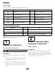
The Toro Warranty A Two-Year Limited Warranty Conditions and Products Covered The Toro Company and its affiliate, Toro Warranty Company, pursuant to an agreement between them, jointly warrant your Toro Commercial product (“Product”) to be free from defects in materials or workmanship for two years or 1500 operational hours*, whichever occurs first. This warranty is applicable to all products with the exception of Aerators (refer to separate warranty statements for these products).