
Operator's Manual
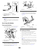


ServicingtheHDDualPoint
Adjusters(DPA)
1.Removeallparts(refertotheInstallationInstructionsfor
theHDDPAKit(ModelNo.120-7230)andtoFigure
33).
2.Applyanti-seizecompoundtotheinsideofthebushing
areaonthecarrierframeofthecuttingunit(Figure33).
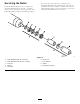
3.Alignthekeysonangebushingstotheslotsinthe
frameandinstallthebushings(Figure33).
4.Installawavewasherontotheadjustershaftandslide
theadjustershaftintotheangebushingsinthecutting
unitframe(Figure33).
5.Securetheadjustershaftwithaatwasherandlock
nut(Figure33).Torquethelocknutto20to27N-m
(15to20ft-lb).
Note:Thebedbaradjustershafthasleft-handthreads.
1
2
3
4
5
6
7
8
9
10
11
g016926
g016926
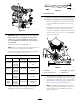
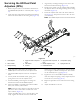
Figure33
1.Shaftadjuster
4.Applyanti-seizecompound
here.
7.Applyanti-seizecompound
here.
10.Compressionspring
2.Wavewasher5.Flatwasher8.Bedbar-adjusterscrew
11.Spring-tensionnut
3.Flangebushing6.Locknut9.Hardenedwasher
6.Applyanti-seizecompoundtothethreadsofthe
bedbar-adjusterscrewthattintotheadjustershaft.
7.Threadthebedbar-adjusterscrewintotheadjuster
shaft.
8.Looselyinstallthehardenedwasher,spring,and
spring-tensionnutontotheadjusterscrew.
9.Installthebedbar,positioningthemountingears
betweenthewasherandthebedbaradjuster.
10.Securethebedbartoeachsideplatewiththebedbar
bolts(nutsonbolts)and6washers.
Note:Positionanylonwasheroneachsideoftheside
plateboss.Placeasteelwasheroutsideeachofthe
nylonwashers(Figure33).
Torquethebedbarboltsto27to36N∙m(240to320
in-lb).Tightenthelocknutsuntiltheoutsidesteel
washerstopsrotatingandendplayisremoved,butdo
notovertightenordeectthesideplates.Thewashers
ontheinsidemayhaveagap(Figure31).
11.Tightenthenutoneachbedbar-adjusterassembly
untilthecompressionspringisfullycompressed,then
loosenthenut1/2turn(Figure32).
12.Repeattheprocedureontheotherendofthecutting
unit.
13.Adjustthebedknifetothereel.
17