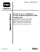
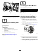
Form No. 3432-369 Rev A 27-inch 5, 8, or 11-Blade or 32-inch 8-Blade EdgeSeries DPA Cutting Unit Reelmaster® 3100-D Traction Unit Model No. Model No. Model No. Model No. Register at www.Toro.com. Original Instructions (EN) 03188—Serial No. 03189—Serial No. 03190—Serial No. 03191—Serial No.
This product complies with all relevant European directives. For details, please see the Declaration of Incorporation (DOI) at the back of this publication. Model No. Serial No. This manual identifies potential hazards and has safety messages identified by the safety-alert symbol (Figure 2), which signals a hazard that may cause serious injury or death if you do not follow the recommended precautions.
Safety Improperly using or maintaining this machine can result in injury. To reduce the potential for injury, comply with these safety instructions and always pay attention to the safety-alert symbol , which means Caution, Warning, or Danger—personal safety instruction. Failure to comply with these instructions may result in personal injury or death. This machine has been designed in accordance with EN ISO 5395 and ANSI B71.4–2017.
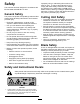
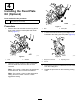
Setup Loose Parts Use the chart below to verify that all parts have been shipped. Procedure 1 2 3 4 Description Use Qty. Straight grease fitting 1 Install the reel grease fitting. No parts required – Adjust the cutting unit O-ring Cap screws (may come assembled) 1 2 Install the reel motors. Fixed plate kit (not included) 1 Install the fixed plate kit (optional). Media and Additional Parts Description Qty.
3 Installing the Reel Motors Parts needed for this procedure: g028640 3. Grease fitting 2. Setscrew 4. Grease vent 2. O-ring 2 Cap screws (may come assembled) Procedure Figure 4 1. Cap screw (2) 1 Important: Before installing the reel motors, obtain and install the counter weights or other accessories on the opposite side of the cutting units from the reel motors as described in the instructions provided with the weights or accessories. Install the straight grease fitting (Figure 4).
4 Installing the Fixed Plate Kit (Optional) Parts needed for this procedure: 1 Fixed plate kit (not included) g011963 Procedure 1. Figure 7 Remove the nuts and washers securing the lift links to the cutting-unit side plate and carrier frame (Figure 7). 1. Nuts 3. 2. Fixed plate Loosen the locknuts securing the height-of-cut brackets to the cutting-unit side plates (Figure 8). g011962 g003326 Figure 6 1. Nuts Figure 8 2. Washers 1. Height-of-cut bracket 3. Adjusting screw 2. Locknut 2.
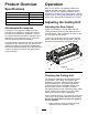
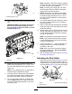
Product Overview Operation Specifications Refer to your traction unit Operator’s Manual for detailed operation instructions. Before using the cutting unit each day, adjust the bedknife; refer to Adjusting the Bedknife to the Reel (page 8). Test the quality of cut by cutting a test swath before using the cutting unit to ensure that the finished cut is correct.
Note: The adjustment knobs have detents corresponding to 0.022 mm (0.0009 inch) bedknife movement for each indexed position. Refer to Adjusting the Bedknife to the Reel (page 8). 2. Test the cutting performance by inserting a long strip of cutting performance paper (Toro Part No. 125-5610) between the reel and the bedknife, perpendicular to the bedknife (Figure 10). Slowly rotate the reel forward; it should cut the paper. g031270 Figure 11 1. Lead-in chamfer on right end of bedknife 2. 6 mm (0.
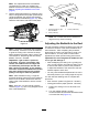
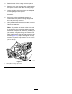
Note: Adjusting 1 side of the cutting unit affects the other side, the 2 clicks will provide clearance for when the other side is adjusted. Note: If starting with a large gap, both sides 7. g003322 Figure 12 1. Bedbar-adjusting screw 3. 8. Tip the cutting unit to expose the bedknife and reel. Important: Make sure that the nuts on the back end of the bedbar-adjusting screws are not resting on the work surface; use the kickstand (Figure 13). 9. 10.
2. Raise the rear of the cutting unit and place a block under the bedknife. 3. Remove the 2 nuts securing each roller bracket and spacer to each side-plate mounting flange. 4. Lower the roller and screws from the side-plate mounting flanges and spacers. 5. Place the spacers onto the screws on the roller brackets. 6. Secure the roller bracket and spacers to underside of side plate mounting flanges with the nuts previously removed. 7. Verify that the bedknife-to-reel contact is correct.
Adjusting the Height of Cut (HOC) 1. Loosen the locknuts securing the height-of-cut brackets to the cutting-unit side plates (Figure 16). g011865 Figure 18 Important: When set properly, the rear and front rollers will contact the gauge bar and the screw will be snug against the bedknife. This ensures that the height-of-cut is identical at both ends of the bedknife. g015089 Figure 16 1. Adjusting screw 3. Height-of-cut bracket 2. Locknut 5. 2.
Height-of-Cut Chart HOC Setting Aggressiveness of Cut No. of Rear Spacers HOC Setting Aggressiveness of Cut No. of Rear Spacers 6 mm (0.250 inch) Less 0 Less 5 Normal 0 38 mm (1.
Use the following chart to determine which bedknife is best suited for the desired height of cut. Bedknife/Height of Cut Chart Bedknife Part No. Bedknife Lip Height Height of Cut Low HOC (Optional) 120-1641 (27 inch) 5.6 mm 6.4 to 12.7 mm 120-1642 (32 inch) (0.220 inch) (0.250 to 0.500 inch) 112-8910 (27 inch) 6.9 mm 9.5 to 63.5 mm 112-8956 (32 inch) (0.270 inch) (0.375 to 2.50 inches)* Standard (Production) 114-9388 (27 inch) 6.9 mm 9.5 to 63.5 mm 114-9389 (32 inch) (0.270 inch) (0.
Height-of-Cut Chart Terms Height-of-Cut Setting (HOC) This corresponds to the desired height of cut. Bench-Set Height of Cut g011863 The bench-set height of cut is the height at which the top edge of the bedknife is set above a flat level surface that contacts the bottom of both the front roller and the rear roller. Figure 21 1. Rear spacers 3. Aggressiveness of cut 2. Side-plate mounting flange Effective Height of Cut Rear Spacers This is the actual height that the grass has been cut.
Maintenance Lubricating the Cutting Units Using the Kickstand when Tipping the Cutting Unit Regularly lubricate the 5 grease fittings of each cutting unit (Figure 23) with No. 2 lithium grease. There are 2 lubrication points on the front roller, 2 on the rear roller, and 1 at the reel-motor spline.
Relief-Grinding the Reel The new reel has a land width of 1.3 to 1.5 mm (0.050 to 0.060 inch) and a 30 degree relief grind. When the land width gets larger than 3 mm (0.120 inch) wide, do the following: 1. Apply a 30 degree relief grind on all reel blades until the land width is 1.3 mm (0.050 inch) wide (Figure 24). g028800 Figure 24 1. 30 degrees 2. 2. 1.3 mm (0.050 inch) Spin grind the reel to achieve <0.025 mm (0.001 inch) reel run-out. Note: This causes the land width to grow slightly.
Servicing the Bedknife The bedknife service limits are listed in the following chart. Important: Operating the cutting unit with the bedknife below the service limit may result in poor after-cut appearance and reduce the structural integrity of the bedknife for impacts. Bedknife Service Limit Chart Bedknife Part No. Bedknife Lip Height* Service Limit* Grind Angles Top/Front Angles Low HOC (Optional) 120-1641 (27 inch) 120-1642 (32 inch) 5.6 mm (0.220 inch) 4.8 mm (0.
3. On each side of the machine, loosen the locknut securing the bedbar bolt (Figure 30). g003334 Figure 30 1. Bedbar bolt g034114 2. Locknut Figure 28 1. Angle-indicator mount 4. 3. Bedknife 2. Edge of the magnet mated 4. Angle indicator with the edge of the bedknife 4. Remove each bedbar bolt, allowing the bedbar to be pulled downward and removed from machine bolt (Figure 30). Account for 2 nylon washers and 1 stamped steel washer on each end of the bedbar (Figure 31).
5. Tighten the spring-tension nut until the spring is collapsed, then back off 1/2 turn (Figure 32). g006505 Figure 32 1. Spring-tension nut 2. Spring Installing the Bedknife 1. g279162 Figure 34 Remove the rust, scale, and corrosion from the bedbar surface and apply a thin layer of oil to the bedbar surface. 1. Bedknife screw tool 2. Clean the screw threads. 2. Install and torque these first to 1 N∙m (10 in-lb). 3.
Servicing the HD Dual Point Adjusters (DPA) 1. 2. 3. Remove all parts (refer to the Installation Instructions for the HD DPA Kit and to Figure 35). Apply anti-seize compound to the inside of the bushing area on cutting unit center frame (Figure 35). Align the keys on flange bushings to the slots in the frame and install the bushings (Figure 35). 4. Install a wave washer onto the adjuster shaft and slide the adjuster shaft into the flange bushings in the frame of the cutting unit (Figure 35). 5.
16. Repeat this procedure on the other end of the cutting unit. Servicing the Roller 17. Adjust the bedknife to the reel; refer to Adjusting the Bedknife to the Reel (page 8). The Roller Rebuild Kit (Part No. 114-5430) and the Roller Rebuild Tool Kit (Part No. 115-0803) (Figure 36) are available for servicing the roller. The Roller Rebuild Kit includes all the bearings, bearing nuts, inner seals, and outer seals to rebuild a roller.
Notes:
Declaration of Incorporation The Toro Company, 8111 Lyndale Ave. South, Bloomington, MN, USA declares that the following unit(s) conform(s) to the directives listed, when installed in accordance with the accompanying instructions onto certain Toro models as indicated on the relevant Declarations of Conformity. Model No. Serial No.
The Toro Warranty Two-Year or 1,500 Hours Limited Warranty Conditions and Products Covered Parts The Toro Company and its affiliate, Toro Warranty Company, pursuant to an agreement between them, jointly warrant your Toro Commercial product (“Product”) to be free from defects in materials or workmanship for 2 years or 1,500 operational hours*, whichever occurs first. This warranty is applicable to all products with the exception of Aerators (refer to separate warranty statements for these products).