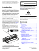
Form No. 3429-845 Rev A 27-inch 5, 8, or 11-Blade or 32-inch 8-Blade EdgeSeries DPA Cutting Unit Reelmaster® 3100-D Traction Unit Model No. Model No. Model No. Model No. Register at www.Toro.com. Original Instructions (EN) 03188—Serial No. 03189—Serial No. 03190—Serial No. 03191—Serial No.
This product complies with all relevant European directives. For details, please see the Declaration of Incorporation (DOI) at the back of this publication. Model No. Serial No. This manual identifies potential hazards and has safety messages identified by the safety-alert symbol (Figure 2), which signals a hazard that may cause serious injury or death if you do not follow the recommended precautions.
Safety Improperly using or maintaining this machine can result in injury. To reduce the potential for injury, comply with these safety instructions and always pay attention to the safety-alert symbol , which means Caution, Warning, or Danger—personal safety instruction. Failure to comply with these instructions may result in personal injury or death. This machine has been designed in accordance with EN ISO 5395 and ANSI B71.4–2017. General Safety This product is capable of amputating hands and feet.
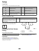
Setup Loose Parts Use the chart below to verify that all parts have been shipped. Procedure 1 2 3 4 Description Use Qty. Straight grease fitting 1 Install the reel grease fitting. No parts required – Adjust the cutting unit O-ring Cap screws (may come assembled) 1 2 Install the reel motors. Fixed plate kit (not included) 1 Install the fixed plate kit (optional). Media and Additional Parts Description Qty.
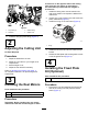
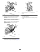
accessories on the opposite side of the cutting units from the reel motors as described in the instructions provided with the weights or accessories. 1. Install the cutting units onto the traction unit; refer to the traction unit Operator’s Manuals for instructions. 2. If there are no cap screws on the reel-motor side plate, install them (Figure 4). 3. Install the O-ring on the reel motor (Figure 5). g028640 Figure 4 1. Cap screw (2) 3. Grease fitting 2. Setscrew 4. Grease vent 2.
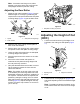
g003326 Figure 8 g011962 1. Height-of-cut bracket Figure 6 1. Nuts 2. 2. Washers Using the number 2 holes, insert a fixed plate onto the bolts and secure it with the nuts removed. Note: The number 1 holes are to be positioned toward the front. Do not reuse the washers. Note: The number 1 hole is a less aggressive setting and the number 3 hole is a more aggressive setting. g011963 Figure 7 1. Nuts 3. 3. Adjusting screw 2. Locknut 2.
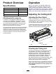
Product Overview Operation Specifications Refer to your traction unit Operator’s Manual for detailed operation instructions. Before using the cutting unit each day, adjust the bedknife; refer to Adjusting the Bedknife to the Reel (page 8). Test the quality of cut by cutting a test swath before using the cutting unit to ensure that the finished cut is correct.
Note: The adjustment knobs have detents corresponding to 0.023 mm (0.0009 inch) bedknife movement for each indexed position. Refer to Adjusting the Bedknife to the Reel (page 8). 2. Test the cutting performance by inserting a long strip of cutting performance paper (Toro Part No. 125-5610) between the reel and the bedknife, perpendicular to the bedknife (Figure 10). Slowly rotate the reel forward; it should cut the paper. g031270 Figure 11 1. Lead-in chamfer on right end of bedknife 2. 6 mm (0.
Note: Adjusting 1 side of the cutting unit affects the other side, the 2 clicks will provide clearance for when the other side is adjusted. Note: If starting with a large gap, both sides should initially be drawn closer by alternately tightening the right and left sides. 7. Slowly rotate the reel so that the same blade that you checked on the right side is crossing the bedknife approximately 25 mm (1 inch) in from the end of the bedknife on the left side of the cutting unit.
Note: If excessive reel drag occurs, either backlap or grind the cutting unit to achieve the sharp edges needed for precision cutting. Adjusting the Rear Roller 1. Adjust the rear roller brackets (Figure 15) to the desired height-of-cut range by positioning the required amount of spacers below the side-plate mounting flange (Figure 15) per the HOC Chart. g020698 Figure 16 1. Side-plate mounting cap screws Adjusting the Height of Cut (HOC) g003324 Figure 15 1. Spacer 3. Side-plate mounting flange 2.
g011864 Figure 18 3. Nut 1. Gauge bar 2. Height-adjusting screw 3. Hook the screw head on the cutting edge of the bedknife and rest the rear end of the bar on the rear roller (Figure 19). 4. Rotate the adjusting screw until the front roller contacts the gauge bar (Figure 19). Adjust both ends of roller until the entire roller is parallel to the bedknife.
Height-of-Cut Chart HOC Setting Aggressiveness of Cut No. of Rear Spacers HOC Setting Aggressiveness of Cut No. of Rear Spacers 6 mm (0.250 inch) Less 0 Less 5 Normal 0 38 mm (1.
Use the following chart to determine which bedknife is best suited for the desired height of cut. Bedknife/Height of Cut Chart Bedknife Part No. Bedknife Lip Height Height of Cut Low HOC (Optional) 120-1641 (27 inch) 5.6 mm 6.4 to 12.7 mm 120-1642 (32 inch) (0.220 inch) (0.250 to 0.500 inch) 112-8910 (27 inch) 6.9 mm 9.5 to 63.5 mm 112-8956 (32 inch) (0.270 inch) (0.375 to 2.50 inches)* Standard (Production) 114-9388 (27 inch) 6.9 mm 9.5 to 63.5 mm 114-9389 (32 inch) (0.270 inch) (0.
Height-of-Cut Chart Terms Height-of-Cut Setting (HOC) This is the desired height of cut. Bench-Set Height of Cut The bench-set height of cut is the height at which the top edge of the bedknife is set above a flat level surface that contacts the bottom of both the front and rear roller. g011863 Figure 22 1. Rear spacers 3. Aggressiveness of cut 2. Side-plate mounting flange Effective Height of Cut This is the actual height to which the grass has been cut.
Maintenance The lubrication points are the front roller (2), the rear roller (2), and the motor spline (1). Using the Kickstand When Tipping the Cutting Unit Note: Lubricating the cutting units immediately after washing helps purge water out of the bearings and increases bearing life.
Servicing the Bedknife The bedknife service limits are listed in the following chart. Important: Operating the cutting unit with the bedknife below the service limit may result in poor after-cut appearance and reduce the structural integrity of the bedknife for impacts. Bedknife Service Limit Chart Bedknife Part No. Bedknife Lip Height* Service Limit* Grind Angles Top/Front Angles Low HOC (Optional) 120-1641 (27 inch) 120-1642 (32 inch) 5.6 mm (0.220 inch) 4.8 mm (0.
3. On each side of the machine, loosen the locknut securing the bedbar bolt (Figure 31). g003334 Figure 31 1. Bedbar bolt g034114 2. Locknut Figure 29 1. Angle-indicator mount 4. 3. Bedknife 2. Edge of the magnet mated 4. Angle indicator with the edge of the bedknife 4. Remove each bedbar bolt, allowing the bedbar to be pulled downward and removed from machine bolt (Figure 31). Account for 2 nylon washers and 1 stamped steel washer on each end of the bedbar (Figure 32).
5. Tighten the spring-tension nut until the spring is collapsed, then back off 1/2 turn (Figure 33). A. Torque the 2 outer screws to 1 N∙m (10 in-lb); refer to Figure 34. B. Working form the center of the bedknife, torque the screws to 23 to 28 N∙m (200 to 250 in-lb); refer to Figure 34. g016648 Figure 33 1. Spring-tension nut 2. Spring Installing the Bedknife 1. g279162 Figure 35 Remove the rust, scale, and corrosion from the bedbar surface and apply a thin layer of oil to the bedbar surface.
Servicing the HD Dual Point Adjusters (DPA) 1. 2. Remove all parts (refer to the Installation Instructions for the HD DPA Kit (Model No. 120-7230) and to Figure 36). 3. Align the keys on flange bushings to the slots in the frame and install the bushings (Figure 36). 4. Install a wave washer onto the adjuster shaft and slide the adjuster shaft into the flange bushings in the cutting unit frame (Figure 36). 5. Secure the adjuster shaft with a flat washer and lock nut (Figure 36).
Servicing the Roller inner seals, and outer seals to rebuild a roller. The Roller Rebuild Tool Kit includes all the tools and the installation instructions required to rebuild a roller with the roller rebuild kit. Refer to your parts catalog or contact your authorized Toro distributor for assistance. The Roller Rebuild Kit (Part No. 114-5430) and the Roller Rebuild Tool Kit (Part No. 115-0803) (Figure 37) are available for servicing the roller.
Notes:
Declaration of Incorporation The Toro Company, 8111 Lyndale Ave. South, Bloomington, MN, USA declares that the following unit(s) conform(s) to the directives listed, when installed in accordance with the accompanying instructions onto certain Toro models as indicated on the relevant Declarations of Conformity. Model No. Serial No.
EEA/UK Privacy Notice Toro’s Use of Your Personal Information The Toro Company (“Toro”) respects your privacy. When you purchase our products, we may collect certain personal information about you, either directly from you or through your local Toro company or dealer.
The Toro Warranty Two-Year or 1,500 Hours Limited Warranty Conditions and Products Covered Parts The Toro Company and its affiliate, Toro Warranty Company, pursuant to an agreement between them, jointly warrant your Toro Commercial product (“Product”) to be free from defects in materials or workmanship for 2 years or 1,500 operational hours*, whichever occurs first. This warranty is applicable to all products with the exception of Aerators (refer to separate warranty statements for these products).