
Operator's Manual

Note:Adjusting1sideofthecuttingunitaffects
theotherside,the2clickswillprovideclearance
forwhentheothersideisadjusted.
Note:Ifstartingwithalargegap,bothsides
shouldinitiallybedrawncloserbyalternately
tighteningtherightandleftsides.
7.Slowlyrotatethereelsothatthesameblade
thatyoucheckedontherightsideiscrossing
thebedknifeapproximately25mm(1inch)in
fromtheendofthebedknifeontheleftsideof
thecuttingunit.
8.Turntheleftbedbaradjusterclockwiseuntilthe
shimcanbeslidthroughthereeltobedknife
gapwithlightdrag.
9.Returntotherightsideandadjustasnecessary
togetlightdragontheshimbetweenthesame
bladeandbedknife.
10.Repeatsteps8and9untiltheshimcanbeslid
throughbothgapswithslightdrag,but1clickin
onbothsidespreventstheshimfrompassing
throughonbothsides.
Note:Thebedknifeisnowparalleltothereel.
Note:Thisprocedureshouldnotbeneeded
ondailyadjustments,butshouldbedoneafter
grindingordisassembly.
11.Fromthisposition(i.e.,1clickinandshimnot
passingthrough)turnthebedbaradjusters
clockwise1clickeach.
Note:Eachclickturnedmovesthebedknife
0.022mm(0.0009inch).Donotovertighten
theadjustingscrews.
12.T estthecuttingperformance;refertoChecking
theCuttingUnit(page7).
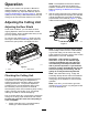
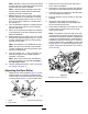
AdjustingtheRearRoller
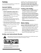
1.Adjusttherearrollerbrackets(Figure11)tothe
desiredheight-of-cutrangebypositioningthe
requiredamountofspacersbelowtheside-plate
mountingange(Figure11)pertheHOCChart.
g003324
Figure11
1.Spacer3.Side-platemountingange
2.Rollerbracket
2.Raisetherearofthecuttingunitandplacea
blockunderthebedknife.
3.Removethe2nutssecuringeachrollerbracket
andspacertoeachside-platemountingange.
4.Lowertherollerandscrewsfromtheside-plate
mountingangesandspacers.
5.Placethespacersontothescrewsontheroller
brackets.
6.Securetherollerbracketandspacersto
undersideofsideplatemountingangeswith
thenutspreviouslyremoved.
7.Verifythatthebedknife-to-reelcontactiscorrect.
Tipthemowertoexposethefrontandrear
rollersandbedknife.
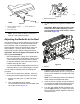
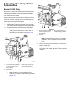
Note:Thepositionoftherearrollertothereel
iscontrolledbythemachiningtolerancesofthe
assembledcomponents;therefore,parallelingis
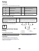
notrequired.Alimitedamountofadjustmentis
possiblebysettingthecuttingunitonasurface
plateandlooseningtheside-platemountingcap
screws(Figure12).Adjustandtightenthecap
screws.T orquethecapscrewsto37to45N·m
(27to33ft-lb).
g020698
Figure12
1.Side-platemountingcapscrews
9