Form No. 3325–354 27” Verticutting Reel Reelmaster 3100-D Attachment Model No. 03217—Serial No.
Contents Introduction . . . . . . . . . . . . . . . . . . . . . . . . . . . . . . . . Safety . . . . . . . . . . . . . . . . . . . . . . . . . . . . . . . . . . . . . Safe Operating Practices . . . . . . . . . . . . . . . . . . . . Safety and Instruction Decals . . . . . . . . . . . . . . . . Specifications . . . . . . . . . . . . . . . . . . . . . . . . . . . . . . . Setup . . . . . . . . . . . . . . . . . . . . . . . . . . . . . . . . . . . . . Replace Center Cutting Unit Pivot Pin . . . . . . . . .
• Remove all debris or other objects that might be picked up and thrown by the verticutting unit reel blades. Keep all bystanders away from the working area. Safety Safe Operating Practices • If the verticutting blades strike a solid object or the unit vibrates abnormally, stop and shut the engine off. Check verticutting unit for damaged parts. Repair any damage before restarting and operating the verticutting unit.
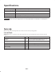
Specifications Reel construction Blades and spacers bolted to square shaft Dethatching range Up to 1/4 in. (6mm) deep blade penetration Blade diameter Power Reel bearings Roller adjustment Important 7–1/4 in. (18.4cm) Hydraulic motor splined to reel shaft Self aligning, roller ball type with cast housing Front roller fixed.
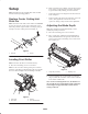
2. Rock verticutting reel on blades, so front roller touches level surface. If a gap between front roller and surface is greater than .010” (.25mm), proceed as follows: Setup Note: Determine the left and right sides of the machine from the normal operating position. • Loosen the lock nuts securing the front roller brackets to the side plates. • Push rearward on the front roller until roller is level on surface, then, tighten the nuts. Do not turn the capscrews—doing so may alter the roller adjustment.
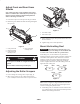
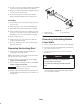
Adjust Front and Rear Grass Shields Note: When operating in turf conditions where much debris is encountered, or unusually heavy thatch, open the front and rear discharge shields to help allow the debris to discharge from the reel. 1. Loosen the capscrews on the pivot of the grass shield. 2. Rotate the grass shield to the desired setting and tighten the capscrew. 2 3 1 2 Figure 5 1. Front roller scraper 2. Rear roller scraper 4 3.
Operation 3. Power requirements to operate the verticutting reels will vary with turf and soil conditions. Travel speed may need to be reduced in some conditions. Training Period 4. When operating in turf conditions where much debris is encountered, or unusually heavy thatch, open the front and rear discharge shields to help allow the debris to discharge from the reel. Before operating the verticutting reels, evaluate the performance of the reel at the desired setting.
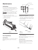
.188 in. dia. (2) Maintenance .625 in. dia. Lubrication .625 in. Each unit has (3) grease fittings that must be lubricated regularly with No. 2 General Purpose Lithium Base Grease. .625 in. 1/4–20 UNC (2) 1. The grease fitting locations and quantities are: reel bearings (2) and carrier frame (1). Note: Lubricate only one reel bearing fitting on each end. 1.05 in. Important Lubricating immediately after washing helps purge water out of bearings and increases bearing life. 1.05 in. Figure 8 2.
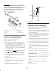
2 2. Loosely secure roller assembly in bench vise and lightly tap one end of roller shaft until free from housing. 3. Remove second bearing from shaft. Support bearing on inner race and tap on roller shaft. 4. Inspect bearings, shaft, and snap ring for damage. Replace damaged components. Re-assemble roller. 1 1 Assembly 1. Press bearing onto one end of shaft. Apply pressure to inner race only. 2. Install snap ring on same end as assembled bearing. 3 3.
Important Do not invert verticutting reel blades. The order of disassembly is extremely important. Do not invert verticutting reel blades when disassembling or reverse the order when assembling. Note the verticutting blades index hole. The index hole is provided for assembly in order to obtain the proper helix for the verticutting reel. .57 .03 This end in vise 1 2 1 Figure 12 1. Seal guard 7 6 Assemble Verticutting Reel 5 4 3 2 1. Inspect bearings and replace if worn or damaged.
The Toro General Commercial Products Warranty A Two-Year Limited Warranty Conditions and Products Covered The Toro Company and its affiliate, Toro Warranty Company, pursuant to an agreement between them, jointly warrant your 1996 or newer Toro Commercial Product (“Product”) purchased after January 1, 1997, to be free from defects in materials or workmanship for two years or 1500 operational hours*, whichever occurs first.