Form No. 3328–881 5, 8 and 11 Blade Cutting Unit Reelmaster 2000/3000 Series Model Model Model Model Model No. 03210—230000001 and No. 03212—230000001 and No. 03237—230000001 and No. 03238—230000001 and No.
Contents Introduction Page Introduction . . . . . . . . . . . . . . . . . . . . . . . . . . . . . . . . 2 Safety . . . . . . . . . . . . . . . . . . . . . . . . . . . . . . . . . . . . . 3 Safety and Instruction Decals . . . . . . . . . . . . . . . 3 Specifications . . . . . . . . . . . . . . . . . . . . . . . . . . . . . . . 3 General Specifications . . . . . . . . . . . . . . . . . . . . 3 Optional Equipment . . . . . . . . . . . . . . . . . . . . . . . 4 Set–Up . . . . . . . . . . . . . . . . . . . . .
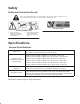
Safety Safety and Instruction Decals Safety decals and instructions are easily visible to the operator and are located near any area of potential danger. Replace any decal that is damaged or lost. Part No. 67-7960 Part No. 93-6688 (for CE) 1. Danger—read and understand the operator’s manual before performing any maintenance. 2. Cutting hazard of hands or feet—stop the engine before approaching reel area. Specifications General Specifications Height-of-cut 3/8 to 1-3/4 in. (10mm to 44mm) 1/2 to 2-5/8 in.
Optional Equipment Basket Kit* (27 in.) High Height of Cut (Extension) Kit* (27 in. & 32 in.) Model No. 03227 Part No. 104-1395 3” Wiehle Roller Kit* (27 in.) Model No. 03233 3” Wiehle Roller Kit* (32 in.) Model No. 03234 Full Roller Kit* (27 in.) Model No. 03440 Full Roller Kit* (32 in.) Model No. 03479 Sectional Roller (27 in.) Part No. 62–4970 Sectional Roller (32 in.) Part No. 94–5982 Anti-Scalp Roller (27 in.) Part No. 63–5090 Anti-Scalp Roller (32 in.) Part No.
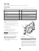
Set–Up Note: Determine the left and right sides of the machine from the normal operating position. Loose Parts Note: Use this chart as a checklist to ensure that all parts have been received. Without these parts, total setup cannot be completed. Description Qty. Use Gasket Screw Cover plate 1 2 1 For use with RM 2300 & RM 2600 cutting units only. O–ring 1 For use with reel motor bearing housing CE Decal 1 Affix to cutting unit for CE. Operator’s manual 1 Read before operating.
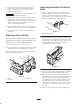
Adjusting Bedknife Parallel to Reel 5. Hold one roller bracket stationary and use other bracket as a wrench to loosen or tighten bearing clearance to allow roller to rotate freely and to eliminate bearing end play. 1. A 3/4 in. (19 mm) wrench will be needed to rotate bedknife adjustment knob. Each notch on the knob will move the bedknife .0005 inches (.013mm) (Fig. 3). Make sure reel contact is removed by rotating bedknife adjustment knob counterclockwise.
Setting Height of Cut and Leveling Rear Roller 6. Loosen the two locknuts securing the bedbar adjuster to the cutting unit side plate (Fig. 5). 1. Position cutting unit on a surface plate. 2. Adjust support capscrew to achieve 1 in. ± 1/16 (25mm ± 1.5mm) dimension between height-of-cut support and front roller bracket (2 places) (Fig. 8). 3 5/8 in. 1 2 2 4 3 Figure 5 1. Bedbar adjuster 2. Locknuts 3. Adjustment nuts 1 in. 7.
6. Place cutting unit on a flat surface and verify that front and rear rollers contact the surface. Alternately push downward on opposite corners of the cutting unit. The amount of clearance allowable under any roller end depends on the turf conditions (sensitivity to lack of parallelism). Generally, .010 to .020 in. (.25 to .50mm) will provide acceptable after cut appearance. If clearance under any roller end is excessive, repeat the leveling of front and rear rollers. 7.
Reposition Rear Roller Changing Height-of-Cut 1. On gauge bar, set head of screw to desired height-of-cut. This measurement is from bar face to underside of screw head. Gauge Bar (Part No. 98–1852) may be obtained from your local Toro Distributor. This procedure describes how to change the height-of-cut after a cutting unit has been set up as described in Setup, page 4. The height-of-cut can be changed with the cutting units on or off the traction unit. 2.
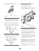
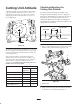
Checking/Adjusting the Cutting Unit Attitude Cutting Unit Attitude Cutting unit attitude refers to the position of the cutting edge of the bedknife behind the center line of the reel (bottom–dead–center) (Fig. 11). This can be varied by changing the position of the front and rear rollers at a given height-of-cut. For setting consistent cutting unit attitude, Toro strongly recommends using a two-screw gauge bar, Toro part no. 98-1852 (Fig. 12).
3. Place the gauge bar across the front and rear rollers. The first screw head needs to fit snugly over the edge of the bedknife while the gauge bar contacts the rollers (Fig. 14). 4. Adjust the second screw to contact the bedknife. 5. Place an angle indicator on the gauge bar and record the gauge bar angle (Fig. 14). 6. Bedknife Angle (step 1) – Gauge Bar Angle (step 5) = Cutting Unit Attitude (degrees) 3 7.
Operation 2. Slowly rotate reel in reverse direction listening for reel-to-bedknife contact. If no contact is evident, turn bedknife adjusting knob clockwise, one click at a time, until light contact is felt and heard. Note: Determine the left and right sides of the machine from the normal operating position. 3. If excessive contact is felt, turn bedknife adjusting knob counterclockwise, one click at a time until no contact is evident.
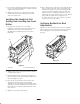
Lubrication Each cutting unit has 6 grease fittings (with optional front roller installed) that must be lubricated regularly with No. 2 General Purpose Lithium Base Grease. The grease fitting locations and quantities are: Bedknife adjuster (2), every 50 hours (Fig. 15); Reel bearings (2) and front and rear rollers (2 ea.) (Fig. 16). Note: Lubricate only one reel bearing grease fitting on each end of cutting unit.
SPA (Single Point Adjustment) Spring Adjustment Backlapping Danger If single point adjustment assembly (Fig. 17) is removed for servicing, make sure spring is compressed, between washers, to a length of .86” (22 mm). This adjustment is attained by tightening nut on SPA knob shaft. While backlapping, reels may stall and then not restart. Contact with the reel blades can cause personal injury or death. Note: SPA assembly has left-handed threads.
The Toro General Commercial Products Warranty A Two-Year Limited Warranty Conditions and Products Covered The Toro Company and its affiliate, Toro Warranty Company, pursuant to an agreement between them, jointly warrant your 1996 or newer Toro Commercial Product (“Product”) purchased after January 1, 1997, to be free from defects in materials or workmanship for two years or 1500 operational hours*, whichever occurs first.