
Operator's Manual

5
Set–Up
Note: Determine the left and right sides of the machine from the normal operating position.
Loose Parts
Note: Use this chart as a checklist to ensure that all parts have been received. Without these parts, total setup cannot be
completed.
Description Qty. Use
Gasket
Screw
Cover plate
1
2
1
For use with RM 2300 & RM 2600 cutting units
only.
O–ring 1 For use with reel motor bearing housing
CE Decal 1 Affix to cutting unit for CE.
Operator’s manual 1 Read before operating.
Parts catalog 1
Registration card 1 Fill out and return to Toro.
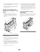
After the cutting unit is unboxed, use the following
procedures to ensure the cutting units are adjusted
properly.
1. Check each end of the reel for grease. Grease should
be visibly evident in the reel bearings.
2. Ensure that all nuts and bolts are securely fastened.
3. Mount front roller.
4. Adjust bedknife to reel.
5. Set height-of-cut and level rear roller.
6. Verify height-of-cut and level front roller.
7. Verify reel to bedknife clearance.
Important Thoroughly read both Cutting Unit and
Traction Unit Operator Manuals. Failure to do so may
result in damage to the cutting unit and/or poor
performance.
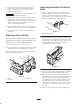
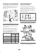
Mounting the Front Roller
(Models 03210 & 03212 only)
1. Remove 2 locknuts securing each angle bracket to
cutting unit (Fig. 1).
1
2
3
4
Figure 1
1. Roller bracket
2. Angle bracket
3. Height-of-cut pin
4. Support capscrew
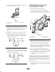
2. Remove height-of-cut pins (Fig. 1).
3. Insert smaller diameter shaft end of roller into white
bushing in roller bracket (Fig. 1), making sure flanged
end of nylon bushing faces inside toward roller. Hex of
roller bracket must mate with hex of adjustment
nut.
4. Install roller bracket onto other shaft end of roller. Hex
of roller bracket must mate with hex of adjustment
nut.