
Operator's Manual

8
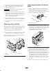
7. Level roller by adjusting appropriate support capscrew
on rear roller supports until roller is parallel and entire
length of roller contacts table.
8. Tighten nuts securing rear roller brackets to angle
brackets. Recheck to ensure that paper will not fit
under each end of roller.
Verifying the Height-of-Cut
Setting and Leveling the Front
Roller
1. On gauge bar, set head of screw to desired
height-of-cut. This measurement is from bar face to
underside of screw head. Gauge Bar (Part No.
98–1852) may be obtained from your local Toro
Distributor.
1
2
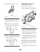
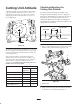
Figure 9
1. Gauge bar 2. Front roller bracket nut
2. Slightly loosen nut securing each front roller bracket
to angle bracket (Fig. 9).
3. Remove hairpin cotters securing front height-of-cut
pins and reinstall in the desired setting as indicated on
the front height-of-cut plate.
4. Place the bar across the front and rear rollers and
adjust the front roller support screws until the
underside of screw head engages the bedknife cutting
edge (Fig. 9). Do this on both ends of reel. Make sure
the rollers are free of debris and/or distortions on the
roller surfaces.
5. Tighten nuts securing roller brackets.
6. Place cutting unit on a flat surface and verify that front
and rear rollers contact the surface. Alternately push
downward on opposite corners of the cutting unit. The
amount of clearance allowable under any roller end
depends on the turf conditions (sensitivity to lack of
parallelism). Generally, .010 to .020 in. (.25 to .50mm)
will provide acceptable after cut appearance. If
clearance under any roller end is excessive, repeat the
leveling of front and rear rollers.
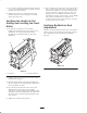
Verifying Bedknife to Reel
Adjustment
With the reels mounted to the traction unit, verify that the
cutting unit will cut one thickness of newspaper across its
entire width (paper to be perpendicular to bedknife)
(Fig. 10).
Figure 10