Form No. 3446-292 Rev A Universal Groomer Drive Kit Reelmaster® 3100-D EdgeSeries™ 27-inch Cutting Units Model No. 03240—Serial No. 321000000 and Up Installation Instructions Introduction This product complies with all relevant European directives. For details, please see the Declaration of Incorporation (DOI) at the back of this publication. Important: Before installing this kit, ensure that you have a compatible cutting unit: 03240 is designed for use on 27-inch Reelmaster DPA Cutting Units.
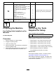
Loose Parts Use the chart below to verify that all parts have been shipped. Procedure 1 2 3 4 5 6 7 Description Qty. Use No parts required – Prepare the machine. Torque wrench (Not included) – Gather the tools required for setup. No parts required – Determine the groomer gearbox position.
Procedure Description 13 Carriage bolt (5/16 x 2-1/4 inches), Part No. 3230-7—sold separately Carriage bolt (5/16 x 3-1/4 inches), Part No. 3230-13—sold separately Carriage bolt (5/16 x 4-1/2 inches), Part No. 3230-30—sold separately Spacer Flange nut (5/16 inch) Locknut (5/16 inch), Part No. 3296-47—sold separately Weight Small weight (Part No. 132-0734-03—sold separately) 14 Qty. 1 1 1 2 1 Install the weights (rear cutting unit with groomer only, with rear grass basket).
3 4 Determining the Groomer Gearbox Position Preparing the Cutting Unit Parts needed for this procedure: No Parts Required 2 Extended splined insert (right-hand threads) 1 Extended splined insert (left-hand threads) Procedure Removing the Front Roller and Height of Cut Brackets Use the following diagram to determine the position of the groomer gearbox and reel motors. 1.
3. Removing the Support Rod Loosen the flange locknut (3/8 inch) and capscrew (3/8 x 3-7/8 inches) in the height-of-cut bracket (Figure 4). Remove the 2 flange-head bolts and washers securing the support rod, and remove the support rod (Figure 5). Note: Discard the support rod and flange-head bolts. g356733 Figure 4 1. Side plate 4. Height-of-cut bracket 2. Flange locknut (3/8 inch) 5. Shaft (roller) 3. Capscrew (3/8 x 3-7/8 inches) 4.
Removing the Splined Insert Assembling the Extended Splined Insert Locking compound solvent: Loctite® 768™ solvent (59 ml (2 oz) Henkel Part No. 768 X-NMS) 1. Restrain the reel to remove the existing splined insert; refer to Restraining the Reel for Removing Threaded Inserts (page 21). 2. Using the reel driveshaft tool (Toro Part No. TOR4074), remove and discard the existing splined inserts from each end of the reel driveshaft (Figure 3).
Assembling the Groomer Gearbox to the Cutting Unit 5 1. Installing the Weight Bracket and the Groomer Drive Box Identify the left drive groomer drive boxes and the right-drive groomer drive boxes; refer to Figure 9. Parts needed for this procedure: 3 Weight bracket 6 Hex-socket, button-head bolt (3/8 x 3/4 inch) 2 Groomer drive box (left drive) 1 Groomer drive box (right drive) g346922 Figure 9 1. Right (yellow) adapter Assembling the Weight Bracket to the Cutting Unit 1. 2.
Important: The reel threads on the left side 6 of the cutting unit are left-handed, and the reel threads on the right side of the cutting unit are right-handed. 4. Restrain the cutting reel; refer to Restraining the Reel for Installing Threaded Inserts (page 22). 5. Torque the hex-head of the gearbox driveshaft to 135 to 150 N∙m (100 to 110 ft-lb). Installing the Idler Assembly Parts needed for this procedure: Important: You must use a 6-point socket with heavy wall.
5. Torque the socket-head screws to 37 to 45 N∙m (27 to 33 ft-lb). 6. Loosely install the 2 locknuts on the pivot hub. to the shoulder bolts prior to installing the adjuster arms to the groomer drive box and the idler assembly. 3.
6. Tighten the locknut on the HOC adjuster bolt, then back off the locknut 1/2 turn (Figure 16). 7. Center the front roller between the HOC bracket assemblies and lock it in place with the cap screws and flange nuts (Figure 16). 8 Installing the Groomer Drive Cap For Cutting Units without a Rear Roller Brush Kit Only g346925 Figure 15 1. Shoulder bolt 3. Adjuster collar 2. Adjuster-arm rod 4. Idler assembly 5.
9 Installing the Groomer Assembly and Optional Broomer Kit Groomer and Broomer Kits Come Separately Parts needed for this procedure: 12 Bolt (1/4 x 1-1/2 inches) 12 Jam nut 12 Shaft clamp 3 Grooming reel (order separately) g240752 Figure 18 Installing the Optional Groomer Kit 1. Drive-stub shaft 4. Shaft clamp (4) 2. Groomer assembly 5. Bolt (4) Torque to 5 to 7 N∙m (46-60 in-lb) 3. Jam nut (4) Ordered Separately Model Number 03241 Groomer 3.
g032402 Figure 21 1. Brush 5. 2. Blade Loosely wrap the straps, as shown in Figure 19, around the groomer reel shaft and brushes inserting the straps in the grooves in the brushes Figure 21. Position the brushes so that the straps are between the following blades: 2 and 3; 12 and 13; 23 and 24 or 24 and 25; 35 and 36, and 45 and 46. Important: You must wrap the straps around g032403 Figure 19 1. Strap buckle 3. Strap 2. Retaining nut 4.
10 Adjusting the Groomer Spring Force (Optional) Parts needed for this procedure: – Washer (Part No. 3256-24, not included) Procedure For low height-of-groom setups where additional spring force is required (only if spring length is above 3/4 inches), install additional washers (Part No. 3256-24) to the eye bolt to compress the height-of-groom springs at a low height of groom. 1. Set the desired cutting unit height of cut; refer to your cutting unit Operator’s Manual. 2.
11 12 Installing the Weights Installing the Weights Groomer Only, with or without Front Grass Baskets and Rear Cutting Unit without Rear Grass Basket Groomer and Rear Roller Brush Installed Parts needed for this procedure: Parts needed for this procedure: 6 Carriage bolt (5/16 x 3-1/2 inches) 6 Spacer 6 Carriage bolt (5/16 x 3-1/2 inches) 6 Flange nut (5/16 inch) 6 Spacer 12 Weight 6 Flange nut (5/16 inch) 18 Weight Procedure For cutting units with the groomer kit and the rear roller
13 Installing the Weights Rear Cutting Unit with Groomer Only, with Rear Grass Basket Parts needed for this procedure: 1 Carriage bolt (5/16 x 2-1/4 inches), Part No. 3230-7—sold separately 1 Carriage bolt (5/16 x 3-1/4 inches), Part No. 3230-13—sold separately g192301 Figure 25 Rear cutting unit with groomer and rear grass basket installed 1 Carriage bolt (5/16 x 4-1/2 inches), Part No. 3230-30—sold separately 2 Spacer 1 Flange nut (5/16 inch) 1. Bolt (5/16 x 4-1/2 inches), sold separately 5.
Operation • The type of grass • The overall management program (i.e., irrigation, fertilizing, spraying, coring, overseeding, etc.) Introduction • Traffic Grooming is performed in the turf canopy above the soil level. Grooming promotes vertical growth of grass plants, reduces grain, and severs stolons, producing a denser turf. Grooming produces a more uniform and tighter playing surface for faster and truer action of the golf ball. • Stress periods (i.e.
Height-of-Cut (HOC) and Height-of-Groom (HOG) Settings Use the Height-of-Cut (HOC) and Height-of-Groom (HOG) table to determine the recommended engagement ranges. HOC and HOG Recommended Range Table (mm) (inch) Number of Rear Roller Spacers 6.3 0.250 9.5 9.5 Height-of-Cut Recommended HOG = HOC Groomer Engagement (mm) (inch) 0 3.1 to 6.3 0.125 to 0.250 0.375 0 4.7 to 9.5 0.187 to 0.375 0.375 1 4.7 to 9.5 0.187 to 0.375 12.7 0.500 0 6.3 to 12.7 0.250 to 0.500 12.7 0.500 1 6.
4. 5. Testing the Groomer Performance At the end of the groomer reel, measure the distance from the lowest tip of the groomer blade to the working surface (Figure 27). Turn the height adjuster knob (Figure 27) to raise or lower the groomer blade tip to the desired height. Important: Improper or over-aggressive use of the grooming reel (i.e., too deep or too frequent grooming) may cause unnecessary stress on the turf, leading to severe damage. Use the groomer cautiously.
Maintenance Transporting the Machine When you wish to mow without the groomer or need to transport the machine, move the quick-up lever to the TRANSPORT position (Figure 29). Changing the Gearbox Lubricant Note: This moves the groomer reel into a raised position. Service Interval After the first 100 hours Every 500 hours / Yearly (Whichever comes first) 1. Clean the external surfaces of the groomer housing.
8. Removing the Groomer Drive Box Use a syringe (Part No. 137-0872) to fill the drive box with 80-90W oil (approximately 90 cc). Note: Retain all removed parts for later installation unless otherwise stated. Important: If you have any issues removing the groomer drive box, refer to your traction unit Service Manual or contact your authorized Toro distributor. g346931 1. Remove the cap from the groomer. 2. Remove the clamp bolts connecting the groomer to the drive box (Figure 18). 3.
Restraining the Reel turn the groomer drive hex-head clockwise (left-hand thread) to remove drive-box shaft from cutting unit WARNING Important: You must use a 6-point socket The cutting reel blades are sharp and capable of amputating hands and feet. with heavy wall. • Keep your hands and feet outside of the reel. Cleaning the Grooming Reel • Ensure that the reel is restrained before servicing it. Service Interval: After each use Clean off the grooming reel after using it by spraying it with water.
Restraining the Reel for Installing Threaded Inserts 1. Insert a long-handled pry bar (recommended 3/8 x 12 inches with a screwdriver handle) through the front of the cutting reel, closest to the side of the cutting unit that you will be torquing (Figure 36). 2. Place the pry bar against the weld side of the internal cutting reel reinforcement (Figure 36). Note: The pry bar should contact a blade at the front, the reel shaft, and a blade at the back of the back of the reel, locking it in place.
Notes:
Declaration of Incorporation The Toro Company, 8111 Lyndale Ave. South, Bloomington, MN, USA declares that the following unit(s) conform(s) to the directives listed, when installed in accordance with the accompanying instructions onto certain Toro models as indicated on the relevant Declarations of Conformity. Model No. 03240 Serial No.