Form No. 3437-865 Rev A Universal Groomer Drive Kit Reelmaster® 3100-D EdgeSeries™ 27-inch Cutting Units Model No. 03240—Serial No. 319000001 and Up Installation Instructions This product complies with all relevant European directives. For details, please see the Declaration of Incorporation (DOI) at the back of this publication. Introduction Read this information carefully to learn how to operate and maintain your product properly and to avoid injury and product damage.
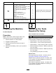
Loose Parts Use the chart below to verify that all parts have been shipped. Procedure 1 2 3 4 5 6 7 8 9 10 Description Qty. Use No parts required – Prepare the machine. Torque wrench (Not included) – Gather the tools required for setup. No parts required – Determine which side the groomer should be installed on.
Procedure Description 11 Carriage bolt (5/16 x 2-1/4 inches), Part No. 3230-7—sold separately Carriage bolt (5/16 x 3-1/4 inches), Part No. 3230-13—sold separately Carriage bolt (5/16 x 4-1/2 inches), Part No. 3230-30—sold separately Spacer Flange nut (5/16 inch) Locknut (5/16 inch), Part No. 3296-47—sold separately Weight Small weight (Part No. 132-0734-03—sold separately) 12 Use Qty.
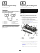
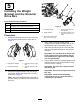
3 4 Determining the Setup Preparing the Cutting Unit No Parts Required Parts needed for this procedure: Procedure Use the following diagram to determine the position of the groomer kits and reel motors. 2 Extended splined insert (right-hand threads) 1 Extended splined insert (left-hand threads) 6 Flange locknut (3/8 inch) Procedure Note: You may discard all removed parts unless otherwise stated. 1. Remove all cutting units from the traction unit; refer to your Operator’s Manual. 2.
. Remove and discard the existing splined insert from each end of the reel shaft using the reel driveshaft tool (Part No. TOR4074 for the 7-inch reel). Refer to Figure 3. 7. Remove the 2 flange-head bolts and washers securing the support rod, and remove the support rod (Figure 5). Note: Retain the flange-head bolts. Important: The splined insert on the left side of the cutting unit has left-hand threads. The splined insert on the right side of the cutting unit has right-hand threads.
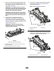
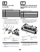
5 Installing the Weight Bracket and the Groomer Drive Box Parts needed for this procedure: 3 Weight bracket 6 Hex-socket, button-head bolt (3/8 x 3/4 inch) 2 Groomer drive box (left drive) 1 Groomer drive box (right drive) g228117 Figure 8 Procedure 1. 1. Internal reel-shaft 4. Groomer drive box (left drive shown) 2. Weight bracket 5. Hex-head (Torque to 135 to 150 N∙m (100 to 110 ft-lb)) 3.
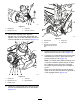
6 7 Installing the Idler Assembly Installing the HOC Bracket Assemblies and the Front Roller Parts needed for this procedure: 6 Hex-socket bolt (3/8 x 3/4 inch) 3 Pivot hub 3 O-ring 1 Idler assembly (left) 2 Idler assembly (right) 6 Jam locknut (3/8 inch) Parts needed for this procedure: Procedure 6 Adjuster pin 6 Cotter pin 3 Left HOC bracket assembly 3 Right HOC bracket assembly 6 Flange locknut (3/8 with 5/8 inch hex) Procedure 1.
g232400 Figure 11 1. Adjuster pin 3. Cotter pin 2. Adjuster-arm rod 4. Groomer drive box 3. On the idler assembly side, align the adjuster-arm rod of the HOC bracket with the adjuster collar on the idler assembly and secure it with an adjuster pin and cotter pin (Figure 12). g192299 Figure 13 1. Adjusting bolt 4. Flange nut 2. Locknut 5. Cap screw 3. Carriage bolt and flange locknut (3/8 with 5/8 inch hex) 5.
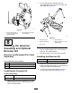
2. Line up the groomer assembly with the drive-stub shafts of the groomer drive box and idler assembly (Figure 15). g279747 Figure 14 1. Set the spring length to 19 mm (3/4 inch) in the engaged position. 2. Optional flange nut (Part No. 3290-357) g240752 Figure 15 8 1. Drive-stub shaft 4. Shaft clamp (4) 2. Groomer assembly 5. Bolt (4) (Torque to 5-7 N∙m (46-60 in-lb)) 3. Jam nut (4) Installing the Groomer Assembly and Optional Broomer Kit Groomer and Broomer Kits Come Separately 3.
g032402 Figure 18 1. Brush 5. 2. Blade Loosely wrap the straps, as shown in Figure 16, around the groomer reel shaft and brushes inserting the straps in the grooves in the brushes Figure 18. Position the brushes so that the straps are between the following blades: 2 and 3; 12 and 13; 23 and 24 or 24 and 25; 35 and 36, and 45 and 46. Important: Wrap the straps around the groomer blade and brush assembly in the primary rotating direction. Figure 17 shows the straps installed for forward rotation.
9 10 Installing the Weights Installing the Weights Groomer Only, with or without Front Grass Baskets and Rear Cutting Unit without Rear Grass Basket Groomer and Rear Roller Brush installed Parts needed for this procedure: Parts needed for this procedure: 6 Carriage bolt (5/16 x 3-1/2 inches) 6 Spacer 6 Carriage bolt (5/16 x 3-1/2 inches) 6 Flange nut (5/16 inch) 6 Spacer 12 Weight 6 Flange nut (5/16 inch) 18 Weight Procedure For cutting units with the groomer kit and the rear roller b
11 Installing the Weights Rear Cutting Unit with Groomer Only, and with Rear Grass Basket) Parts needed for this procedure: 1 Carriage bolt (5/16 x 2-1/4 inches), Part No. 3230-7—sold separately 1 Carriage bolt (5/16 x 3-1/4 inches), Part No. 3230-13—sold separately g192301 Figure 21 Rear cutting unit with groomer and rear grass basket installed 1 Carriage bolt (5/16 x 4-1/2 inches), Part No. 3230-30—sold separately 2 Spacer 1 Flange nut (5/16 inch) 1.
g298196 Figure 22 1. Hex-socket screw 2. Clutch-knob assembly Important: Do not install caps on Universal Groomer assemblies with rear roller brush kits installed. 2. Apply medium-strength cylindrical bonding retaining compound (such as Green Loctite 609®) around the snap ring groove and the outer diameter surface (Figure 23). 3. Install the cap as shown in Figure 23. g299664 Figure 23 1. Cap 2.
Operation • The type of grass • The overall management program (i.e., irrigation, fertilizing, spraying, coring, overseeding, etc.) Introduction • Traffic Grooming is performed in the turf canopy above the soil level. Grooming promotes vertical growth of grass plants, reduces grain, and severs stolons, producing a denser turf. Grooming produces a more uniform and tighter playing surface for faster and truer action of the golf ball. • Stress periods (i.e.
Adjusting the Groomer Height 1. Park the machine on a clean and level surface, lower the cutting units completely to the ground, shut off the engine, engage the parking brake, and remove the key. 2. Make sure that the rollers are clean and the cutting unit is set to the desired height-of-cut (see your cutting unit Operator’s Manual). 3. Rotate the quick-up levers (Figure 25) to the ENGAGED position (the handle points toward the front of the cutting unit.
Height-of-Cut (HOC) and Height-of-Groom (HOG) Recommended Range Height-of-Cut (mm) Height-of-Cut (inch) Number of Rear Roller Spacers Recommended HOG = HOC Groomer Engagement Recommended HOG = HOC Groomer Engagement (mm) (inch) 6.3 0.250 0 3.1 to 6.3 0.125 to 0.250 9.5 0.375 0 4.7 to 9.5 0.187 to 0.375 9.5 0.375 1 4.7 to 9.5 0.187 to 0.375 12.7 0.500 0 6.3 to 12.7 0.250 to 0.500 12.7 0.500 1 6.3 to 12.7 0.250 to 0.500 12.7 0.500 2 6.3 to 9.5 0.250 to 0.375 15.8 0.
Changing the Groomer Operating Direction Testing the Groomer Performance The groomer has 3 settings: NEUTRAL (N), FORWARD (F), and REVERSE (R). To change the direction of the groomer, turn the knob at the end of the groomer drive box and align the desired position with the adjustment notch. Important: Improper or over-aggressive use of the grooming reel (i.e., too deep or too frequent grooming) may cause unnecessary stress on the turf, leading to severe damage. Use the groomer cautiously.
Maintenance Changing the Gearbox Lubricant Service Interval After the first 100 hours Every 500 hours / Yearly (Whichever comes first) 1. 2. 3. 4. 5. Clean the external surfaces of the groomer housing. g240898 Figure 28 Important: Ensure that there is no dirt or clippings on the outside of the groomer housing; if debris gets inside of the groomer it can damage the gearbox. Remove the drain plug on the bottom of the housing (Figure 29).
Removing the Groomer Drive Box Important: If the groomer drive box is installed on the left side of a cutting unit, turn the groomer drive hex-head clockwise (left-hand thread) to remove drive-box shaft from cutting unit Note: Retain all removed parts for later installation unless otherwise stated. Important: You must use a 6-point socket Important: If you have any issues removing the with heavy wall.
Restraining the Reel WARNING The cutting reel blades are sharp and capable of amputating hands and feet. • Keep your hands and feet outside of the reel. • Ensure that the reel is restrained before servicing it. Restraining the Reel for Removing Threaded Inserts 1. 2. 3. Loosen the shield-bolt on the left side of the cutting unit and raise the rear shield (Figure 32).
Restraining the Reel for Installing Threaded Inserts 1. Insert a long-handled pry bar (recommended 3/8 x 12 inches with a screwdriver handle) through the front of the cutting reel, closest to the side of the cutting unit that you will be torquing (Figure 33). 2. Place the pry bar against the weld side of the internal cutting reel reinforcement (Figure 33). Note: The pry bar should contact a blade at the front, the reel shaft, and a blade at the back of the back of the reel, locking it in place.
Declaration of Incorporation The Toro Company, 8111 Lyndale Ave. South, Bloomington, MN, USA declares that the following unit(s) conform(s) to the directives listed, when installed in accordance with the accompanying instructions onto certain Toro models as indicated on the relevant Declarations of Conformity. Model No. 03240 Serial No.
EEA/UK Privacy Notice Toro’s Use of Your Personal Information The Toro Company (“Toro”) respects your privacy. When you purchase our products, we may collect certain personal information about you, either directly from you or through your local Toro company or dealer.
The Toro Warranty Two-Year or 1,500 Hours Limited Warranty Conditions and Products Covered Parts The Toro Company and its affiliate, Toro Warranty Company, pursuant to an agreement between them, jointly warrant your Toro Commercial product (“Product”) to be free from defects in materials or workmanship for 2 years or 1,500 operational hours*, whichever occurs first. This warranty is applicable to all products with the exception of Aerators (refer to separate warranty statements for these products).