
Installation Instructions
6
InstallingtheIdler
Assembly
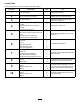
Partsneededforthisprocedure:
6
Hex-socketbolt(3/8x3/4inch)
3Pivothub
3
O-ring
1
Idlerassembly(left)
2
Idlerassembly(right)
6
Jamlocknut(3/8inch)
Procedure
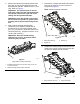
1.Positiontheidlerassemblyontheoppositeside
ofthereelfromthegroomerdrivebox.
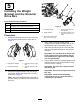
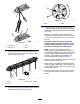
2.InstalltheO-ringontothepivot-hubassembly.
3.Applyanti-seizecompoundontheoutside
diameterofthepivot-hubassembly(Figure9).
g192297
Figure9
1.Jamlocknut—3/8inch(2)4.O-ring
2.Hex-socketbolt(3/8x3/4
inch)
5.Idlerassembly(rightside
shown)
3.Pivothub6.Applyanti-seize
compoundontheoutside
diameterofthehub.
4.Securethepivothubovertheidlerassemblyto
thereelusing2hex-socketbolts(3/8x3/4inch)
(Figure9).
5.Looselyinstallthe2locknutsonthepivothub
(Figure9).
7
InstallingtheHOCBracket
AssembliesandtheFront
Roller
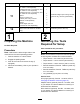
Partsneededforthisprocedure:
6Adjusterpin
6
Cotterpin
3
LeftHOCbracketassembly
3
RightHOCbracketassembly
6
Flangelocknut(3/8with5/8inchhex)
Procedure
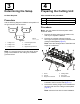
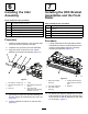
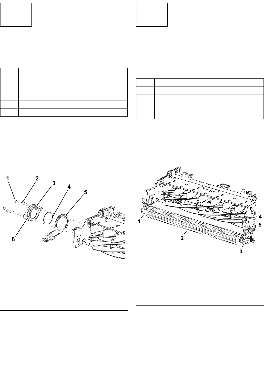
1.LooselyinstalltheleftandrightHOCbracket
assembliesandthefrontrollerassemblytothe
cutting-unitsideplatesusingthepreviously
removedcarriagebolts(Figure10).
g246878
Figure10
1.RightHOCbracket
assembly
4.Carriageboltandange
locknut(3/8with5/8inch
hex)
2.Frontrollerassembly5.Washers
3.LeftHOCbracket
assembly
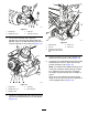
2.Ontheleftside,slidetheadjuster-armrodofthe
HOCbracketintothegaponthegroomerdrive
boxandsecureitwithanadjusterpinandcotter
pinasshowninFigure11.
7