
Installation Instructions
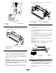
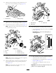

21.Makesurethatthesealliponeachexcluderseal,isin
lightcontactwitheachbearinghousing(Figure14).
Figure14
1.Excluderseal2.Bearinghousing
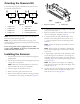
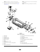
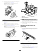
22.Mountthedrivesidequick-upassembliestotheside
plateswith3/8x3/4inchangeheadbolt(Figure15).
23.Installnewdrivepully,keyandangescrew(Figure15).
Note:Applyneverseizeonkeyholeandtorquescrew
to37-44Nm(27-33ftlbs)
2
3
4
g027773
1
5
6
Figure15
1.Keyhole4.Flangenut
2.Key5.Flangescrew
3.Pulley
6.Quick-upassembly
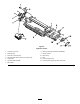
24.Installthegroomerbeltontothepulleys(Figure16).
Note:Makesurethattheribsonthebeltareproperly
seatedinthegroovesoneachpulley.
25.Hooktheidlerspringintheholeintheidlerplatetab
andaroundthegrooveonthegroomerplatelower
stud(Figure16).
Note:Theopenendofthespringhookistobe
positionedtowardthedrivepulley.
g027776
1
2
3
Figure16
1.Idlerplatetab3.Lowerstud
2.Idlerspring
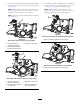
26.Checkthealignmentofthebelt/pulleysasfollows:
•Layastraightedgealongtheouterfaceofthedrive
pulley(Figure17).
Important:Donotusetheidlerpulleyto
checkalignment.
Figure17
•Theouterfacesofthedriveanddrivenpulleys
shouldbeinlinewithin.030inch.
•Ifthepulleysarenotaligned,refertoAligningthe
PulleyandBelt(page15).
•Ifthepulleysarealigned,continuewiththe
installation.
Important:Thebeltmayfailprematurelyifthe
pulleysarenotproperlyaligned.
9