Form No. 3350–408 Reelmaster 2000-D Traction Unit Model No.
Operation . . . . . . . . . . . . . . . . . . . . . . . . . . . . . . . . . . Controls . . . . . . . . . . . . . . . . . . . . . . . . . . . . . . . . Starting and Stopping the Engine . . . . . . . . . . . . . Bleeding the Fuel System . . . . . . . . . . . . . . . . . . . Checking the Operation of the Interlock Switches Towing the Traction Unit . . . . . . . . . . . . . . . . . . . Operating Characteristics . . . . . . . . . . . . . . . . . . . Selecting the Clip Rate (Reel Speed) . . . . . . . . . .
Introduction Read this manual carefully to learn how to operate and maintain your product properly. The information in this manual can help you and others avoid injury and product damage. Although Toro designs and produces safe products, you are responsible for operating the product properly and safely. attention to the safety alert symbol, which means CAUTION, WARNING, or DANGER—“personal safety instruction.” Failure to comply with the instruction may result in personal injury or death.
Preparation – stay alert for humps and hollows and other hidden hazards; • While mowing, always wear substantial footwear, long trousers, hard hat, safety glasses, and ear protection. Long hair, loose clothing, or jewelry may get tangled in moving parts. Do not operate the equipment when barefoot or wearing open sandals. – never mow across the face of the slope, unless the mower is designed for this purpose. • Stay alert for holes in the terrain and other hidden hazards.
• Reduce the throttle setting during engine run-out and, if the engine is provided with a shut-off valve, turn the fuel off at the conclusion of mowing. • Carefully release pressure from components with stored energy. • Disconnect battery and remove spark plug wire before making any repairs. Disconnect the negative terminal first and the positive last. Reconnect positive first and negative last. • Keep hands and feet away from the cutting units.
• To ensure safety and accuracy, have an Authorized Toro Distributor check the maximum engine speed with a tachometer. Maximum governed engine speed should be 3200 RPM. – Do not drive close to sand traps, ditches, creeks, or other hazards. – Reduce speed when making sharp turns. Avoid sudden stops and starts. • If major repairs are ever needed or if assistance is desired, contact an Authorized Toro Distributor. – When near or crossing roads, always yield the right-of-way.
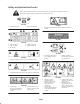
Safety and Instruction Decals Safety decals and instructions are easily visible to the operator and are located near any area of potential danger. Replace any decal that is damaged or lost. 93-7267 1. Lock parking brake 93-6696 2. Unlock parking brake 1. Warning—spring loaded mechanism. Read the operator’s manual. 67-5360 94-5056 1. Slow reel speed 2. Fast reel speed 3. Reel height 4. 5 Blade cutting unit 5. 8 Blade cutting unit 93-6668 1. The battery contains lead. Do not dispose of in the garbage.
93-7276 1. 2. 3. 4. 106-5976 Explosion hazard—wear eye protection. Caustic liquid hazard—flush skin with water. Fire hazard—sparks, flame, and smoking prohibited. Poison—keep children away from the battery. 1. Engine coolant under pressure 2. Explosion hazard—read the Operator’s Manual. 106-8109 8 3. Warning—do not touch the hot surface. 4. Warning—read the Operator’s Manual.
104-3991 9
4-3994 (Affix over decal part no. 104–3991 for CE) 1. Read the Operator’s Manual. 2. Warning—read the Operator’s Manual. Do not use starting fluid. 3. 4. 5. 6. Raise and lower the reels. Lower the reels. Neutral Raise the reels. 7. 8. 9. 10. 10 Power take-off (PTO) Pull on Push off Engine—stop 11. 12. 13. 14.
Specifications Note: Specifications and design subject to change without notice. General Specifications Configuration Engine Tricycle vehicle with 2-wheel traction drive and rear wheel steering. Briggs & Stratton–Daihatsu, 4-cycle, 3-cylinder, liquid cooled, vertical OHV, diesel engine with centrifugal water pump. 18.4 hp (13.7 kW); governed to a maximum speed of 3200 RPM. 51.9 cu. in. (850 cc) displacement. Forced lubrication gear pump. Mechanical centrifugal governor. Mechanical fuel transfer pump.
Measurements Wheel tread width Wheel base Width Optional Equipment 54-1/2 in. (138 cm) 55 in. (140 cm) 76-1/2 in. (194 cm) Transport width with 27″ cutting units 72 in. (183 cm) with 32″ cutting units 85 in. (216 cm) Standard Seat Model No. 03224 Suspension Seat Model No. 03225 3–Wheel Drive Kit Model No. 03429 Weight Kit Part No. 94-3698 Rear Weight Kit Part No. 83-9370 Rear Weight Part No. 83-9390 27” Lift Arm Kit Model No. 03471 Length 96 in. (244 cm) 5 Blade Cutting Unit Model No.
Setup Note: Determine the left and right sides of the machine from the normal operating position. Loose Parts Note: Use this chart as a checklist to ensure that all parts necessary for assembly have been received. Without these parts, total setup cannot be completed. Some parts may have already been assembled at the factory. Description Qty. Use Wheel assembly 1 Lug nut 4 Seat stop bracket 1 Capscrew 5/16 x 1 in.
Description Qty. Instrument panel decal 1 Parts catalog 1 Certificate of compliance 1 Operator video 1 Operator’s manual 2 Engine operator’s manual 1 Registration card 1 Installing the Rear Wheel Use Affix to instrument panel for European compliance. View before operating the machine. Read before operating the machine. Fill out and return to Toro. 3. On the Suspension Seat, check the alignment of the mounting holes with the seat plate.
5. Tighten the flange nuts and check the operation of the seat. is not 1/4 in. (6 mm), an adjustment to the lift cylinder is required. If the distance is correct, remove the carrier frame and proceed with the setup instructions. 6. When mounting a standard seat to machine, a seat stop (Fig. 3) must be installed as follows: 3 1 A. Move seat forward. B. Remove capscrew and nut securing water separator bracket to underside of skirt. 3 C.
7 1 1 2 6 2 3 8 4 3 5 Figure 5 1. Carrier frame 2. Mounting link 3. Bearing housing cover Figure 7 1. 2. 3. 4. Installing the Front Lift Arms 1. Insert a pivot rod into the left lift arm and align the mounting holes (Fig. 6). 2. Secure the pivot rod to the lift arm with a capscrew (5/16 x 7/8 in.) and lock washer. Counterbalance arm Top capscrew Bottom capscrew Lift arm pivot pin 5. 6. 7. 8. Tipper chain Lift chain Cylinder pin Lift arm tab 4.
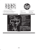
Mounting the Cutting Unit Drive Motors 2 1. Position the cutting units in front of the pivot rods. 2. Remove the bearing housing cover (Fig. 5) from the inside end of the right-hand cutting unit. Install the cover and gasket (supplied with the cutting unit) on the outside end. Locate the spider coupling (Fig. 9) shipped in the bearing housing. 3 3. Insert the O-ring (supplied with the cutting unit) on the flange of the drive motor (Fig. 9). 1 4.
The counterbalance springs help balance the cutting units to allow equal amounts of weight (down pressure) to be distributed to each end of the cutting unit. The springs also transfer weight from the cutting units to the traction unit therefore, increasing traction. Note: Increasing the spring tension will reduce the weight on the inboard end of the cutting unit, increase the weight on the outboard end of the cutting unit, and increase traction. Decreasing the spring tension has the opposite affect.
32” Cutting Units 4 1 1. Mount a spring anchor to the rear inboard side of each front cutting unit lift tab with 2 capscrews (1/4 x 3/4 in.) and locknuts, as shown in Figure 15. 2 2 5 3 1 Figure 16 1. 2. 3. 4. 5. Clevis pin and cotter pin 6. Chain, clevis, and clevis pin 6. On the rear counterbalance arms, install the vinyl cover over the spring before hooking the other end of the spring into the spring shackle in the second hole from the top (Fig. 17). Figure 15 1.
Adding Rear Ballast Activating and Charging the Battery This unit complies with ANSl B71.4–1999 Standard and all applicable European requirements when equipped with rear ballast. Use the following chart to determine the weight or combinations of weights needed.
Important Do not overfill the battery. Electrolyte will overflow onto other parts of the machine and severe corrosion and deterioration will result. 5. Install the positive cable (red) to the positive (+) terminal and the negative cable (black) to the negative (—) terminal of the battery (Fig. 18) and secure them with capscrews and nuts. Slide the rubber boot over the positive terminal to prevent a possible short from occurring.
Before Operating Caution 1 If you leave the key in the ignition switch, someone could accidently start the engine and seriously injure you or other bystanders. Before servicing or making adjustments to the machine, stop the engine and remove the key from the ignition switch. Checking the Crankcase Oil The engine is shipped with approximately 3.5 quarts (w/ filter) of oil in the crankcase; however, level of oil must be checked before and after the engine is first started. Figure 20 1. Filler cap 1.
Note: After filling or changing oil, start and run the engine at idle for 30 seconds. Shut engine off. Wait 30 seconds and check oil level. Add enough oil to raise level to FULL mark on dipstick. 4. Wipe up any fuel that may have spilled to prevent a fire hazard. Filling the Fuel Tank The cooling system is filled with a 50/50 solution of water and permanent ethylene glycol anti-freeze. Check the coolant level at the beginning of each day before starting the engine.
Checking the Hydraulic System Fluid Caution If the engine has been running, the pressurized, hot coolant can escape and cause burns. The machines reservoir is filled at the factory with approximately 3.3 gallons (12.5 l) of high quality hydraulic fluid. Check the level of hydraulic fluid before the engine is first started and daily thereafter. Appropriate hydraulic oils are listed below. • Do not open the radiator cap when the engine is running.
Checking the Tire Pressure multi-viscosity hydraulic fluids which allows operation at lower temperatures without the increased viscosity, which is associated with straight viscosity fluids. The tires are over-inflated for shipping. Therefore, release some of the air to reduce the pressure. The correct air pressure in the tires is 16–20 psi (110–138 kPa).
Operation The reverse pedal stop (under the pedal) (Fig. 28) is set at the factory to provide 3 MPH maximum speed in reverse. Note: Determine the left and right sides of the machine from the normal operating position. Starter Switch The starter switch (Fig. 30), used to start, stop, and preheat the engine, has three positions: OFF, ON, and START. Rotate the key clockwise to ON position and hold until glow plug light goes out. Then rotate the key clockwise (START position) to engage the starter motor.
Cutting Unit Drive Switch Reel Engage Indicator The switch (Fig. 30) has two positions: ENGAGE and DlSENGAGE. The push-pull switch operates a solenoid valve on the valve bank, to drive the cutting units. The reel engage indicator light (Fig. 31) will glow when reels are lowered to cutting position. Parking Brake Hour Meter Whenever the engine is shut off, the parking brake must be engaged to prevent accidental movement of the machine. To engage the parking brake, pull back on the lever.
Starting and Stopping the Engine Inclining Backrest (Fig. 33)—Turn the handle to adjust the angle of the backrest (Deluxe Seat only). 2 Important The fuel system may have to be bled if any of the following situations have occurred: 3 • Initial start up of a new engine. • Engine has ceased running due to lack of fuel. • Maintenance has been performed upon fuel system components; i.e. filter replaced, etc. 1 Refer to Bleeding the Fuel System. 1.
Bleeding the Fuel System Checking the Operation of the Interlock Switches 1. Unlatch and raise the hood. 2. Loosen air bleed screw on top of fuel filter/water separator (Fig. 35). Caution If safety interlock switches are disconnected or damaged the machine could operate unexpectedly causing personal injury. 2 • Do not tamper with the interlock switches. • Check the operation of the interlock switches daily and replace any damaged switches before operating the machine.
Towing the Traction Unit Follow the operating guidelines presented in this manual and know how to operate the machine safely on all types of terrain. Hills (or slopes) over 15 degrees should be traversed or mowed up and down, not side to side, and hills over 20 degrees should generally be avoided unless special safeguards, skills, and conditions exist. Always plan well ahead to avoid the need for sudden stops, starts, or turns. To stop, use the reverse pedal for braking.
Variable Reel Speed Selection Chart—5 Blade Reel Variable Reel Speed Selection Chart—8 Blade Reel Height of Cut (in.) 3WD Speeds 3–5 MPH 2WD Speeds 6–7 MPH Height of Cut (in.) 3WD Speeds 3–5 MPH 2WD Speeds 6–7 MPH 2-1/2 (2.50) 3 5 2-1/2 (2.50) 3* 3 2-3/8 (2.38) 3 5 2-3/8 (2.38) 3* 3 2-1/4 (2.25) 4 5 2-1/4 (2.25) 3* 3 2-1/8 (2.13) 4 5 2-1/8 (2.13) 3* 3 2 (2.00) 4 6 2 (2.00) 3* 3 1-7/8 (1.88) 4 6 1-7/8 (1.88) 3 4 1-3/4 (1.75) 5 7 1-3/4 (1.75) 3 4 1-5/8 (1.
Training Period Inspection and Clean-Up After Mowing Before mowing with the machine, we suggest that you find a clear area and practice starting and stopping, raising and lowering cutting units, turning, etc. This training period will be beneficial to the operator in gaining confidence in the performance of the machine.
Standard Control Module (SCM) Output circuits are energized by an appropriate set of input conditions. The three outputs include PTO, ETR, and START. Output LED’s monitor relay condition indicating the presence of voltage at one of three specific output terminals. The Standard Control Module is a ”potted” electronic device produced in a ”one size fits all” configuration.
Each row (across) in the logic chart below identifies input and output requirements for each specific product function. Product functions are listed in the left column. Symbols identify specific circuit condition including: energized to voltage, closed to ground, and open to ground. – Indicates a circuit closed to ground. – LED ON O Indicates a circuit open to ground or de–energized – LED OFF + Indicates an energized circuit (clutch coil, solenoid, or start input) LED ON.
Maintenance Note: Determine the left and right sides of the machine from the normal operating position. Recommended Maintenance Schedule Maintenance Service Interval Maintenance Procedure After first 10 hours • • • • • • After first 50 hours • Check the engine RPM (idle and full throttle). Every 50 hours • Inspect the air filter, dust cup, and burp valve. • Lubricate all grease fittings. • Check the engine belt tension. Every 100 hours • Change the engine oil filter.
Daily Maintenance Checklist Duplicate this page for routine use. For the week of: Maintenance Check Item Mon. Tues. Wed. Thurs. Check the safety interlock operation. Check the brake operation. Check the engine oil level. Check the cooling system fluid level. Drain the water/fuel separator Check the air filter, dust cup, and burp valve. Check the oil cooler, radiator and screen for debris. Check for unusual engine noises.1 Check for unusual operating noises. Check the hydraulic system oil level.
Service Interval Chart Caution If you leave the key in the ignition switch, someone could accidently start the engine and seriously injure you or other bystanders. Remove the key from the ignition and disconnect the wire from the spark plug before you do any maintenance. Set the wire aside so that it does not accidentally contact the spark plug.
Greasing the Bearings and Bushings The traction unit has grease fittings that must be lubricated regularly with No. 2 General Purpose Lithium Base Grease. If the machine is operated under normal conditions, lubricate bearings and bushings after every 50 hours of operation. Bearings and bushings must be lubricated daily when operating conditions are extremely dusty and dirty. Dusty and dirty operating conditions could cause dirt to get into the bearings and bushings, resulting in accelerated wear.
4. Reverse the procedure to install the hood. General Air Cleaner Maintenance Check the air cleaner body for damage which could possibly cause an air leak. Replace a damaged air cleaner body. Service the air cleaner filter every 200 hours (more frequently in extreme dusty or dirty conditions). Do not over-service the air filter. Figure 43 Be sure that the cover is sealing around the air cleaner body. Servicing the Air Cleaner 1.
Changing Engine Oil And Filter B. Keep the air hose nozzle at least 2 in. (51 mm) from the filter and move the nozzle up and down while rotating the filter element. Inspect the filter for holes and tears by looking through the filter toward a bright light. Change oil and filter initially after the first 50 hours of operation, thereafter, change oil and filter every 100 hours. 1. Park the machine on a level surface, lower the cutting units, set the parking brake, and turn the engine off. 5.
2. If only the filter is to be changed, remove the reservoir cap and insert the reservoir plug (Fig. 50) to block the outlet. This will retain most of the fluid in the reservoir when the filter is removed. 7. Run the engine until the lift cylinders extend and retract and forward and reverse wheel motion is achieved. 8. Stop the engine and check the oil level in the reservoir. Add oil if necessary. 9. Check all connections for leaks.
Fuel System 1 1 Fuel Lines and Connections Check lines and connections every 400 hours or yearly, whichever comes first. Inspect for deterioration, damage, or loose connections. 1 Fuel Filter/Water Separator Drain water or other contaminants from fuel filter/water separator daily by loosening drain plug (Fig. 54) on filter canister. Tighten plug after draining. Replace filter canister after every 400 hours of operation. Figure 55 1. Clean area around filter canister mounting surface. 1.
1 1 Figure 56 Figure 57 1. Traction adjustment cam 1. Neutral switch Warning 3. Adjust switch location until circuit is made when in neutral and broken with 1 inch travel of traction pedal. The engine must be running so a final adjustment of the traction adjustment cam can be performed. Contact with hot or moving parts can result in personal injury. 4. Tighten the locknut Keep hands, feet, face, and other body parts away from the muffler, other hot parts of the engine, and other rotating parts.
Alternator belt 1. Check tension by depressing belt at mid span of crankshaft and alternator pulleys with 22 lbs. of force. A new belt should deflect .3–.5 in. A used belt should deflect .4–.55 in. If deflection is incorrect, proceed to next step. If correct, continue operation. 1 2. To adjust belt tension: A. Loosen alternator mounting bolts. B. Using a bar, rotate alternator until proper belt tension is attained, then tighten mounting bolts. 2 Figure 60 1.
Adjusting the Hand Brake Danger 1. Remove both front wheels. 2. Make sure that the brake is in the OFF position. Battery electrolyte contains sulfuric acid which is a deadly poison and causes severe burns. 3. Loosen the jam nut on the clevis. Remove the cotter pin securing the top of the clevis to the upper brake lever (Fig. 62). Rotate the clevis, one turn at a time, to decrease the distance between the levers. • Do not drink electrolyte and avoid contact with skin, eyes or clothing.
Backlapping avoid quick deterioration of the charge in the battery. To prevent the battery from freezing, make sure it is fully charged. The specific gravity of a fully charged battery is 1.265 – 1.299. Danger Fuses While backlapping, the reels may stall and then restart. Placing your hands or feet in the reel area while backlapping will result in injury or death. The fuses in the electrical system are located on the back of the instrument panel (Fig. 63).
Caution Contact with the reel or other moving parts can result in personal injury. 7. To make an adjustment to the cutting units while backlapping, turn the reels OFF by pushing in on the knob on the instrument panel and turning the engine OFF. After adjustments have been completed, repeat steps 4–6. 8.
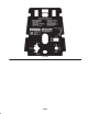
Electrical Schematic 48
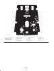
Hydraulic Schematic 49
The Toro General Commercial Products Warranty A Two-Year Limited Warranty Conditions and Products Covered The Toro Company and its affiliate, Toro Warranty Company, pursuant to an agreement between them, jointly warrant your Toro Commercial Product (“Product”) to be free from defects in materials or workmanship for two years or 1500 operational hours*, whichever occurs first.