Form No. 3397-737 Rev A 18in and 22in 8 and 11 Blade DPA Cutting Unit Reelmaster® 3550 Series Traction Unit Model No. Model No. Model No. Model No. Register at www.Toro.com. Original Instructions (EN) 03480—Serial No. 03481—Serial No. 03482—Serial No. 03483—Serial No.
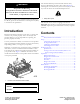
This manual identifies potential hazards and has safety messages identified by the safety-alert symbol (Figure 2), which signals a hazard that may cause serious injury or death if you do not follow the recommended precautions. WARNING CALIFORNIA Proposition 65 Warning This product contains a chemical or chemicals known to the State of California to cause cancer, birth defects, or reproductive harm. Figure 2 1. Safety-alert symbol This product complies with all relevant European directives.
Safety clothing which could get caught in moving parts. Always wear long pants. Wearing safety glasses, safety shoes, and a helmet is advisable and required by some local ordinances and insurance regulations. This machine has been designed in accordance with EN ISO 5395:2013. • Remove all debris or other objects that might be picked Improper use or maintenance of this equipment can result in injury or death. To reduce the potential for injury or death, comply with the following safety instructions.
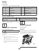
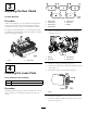
Setup Loose Parts Use the chart below to verify that all parts have been shipped. Procedure Description 1 2 3 4 Use Qty. Cutting unit 1 Inspect the cutting unit. No parts required – Use the kickstand when tipping the cutting unit. No parts required – Adjust the rear shield. Straight grease fitting O-ring 1 1 Install the loose parts. Media and Additional Parts Description Parts Catalog Operator's Manual Qty. Use 1 1 Review these materials and save them for future reference.
3 Adjusting the Rear Shield No Parts Required Figure 5 Procedure Under most conditions, you can attain the best dispersion when the rear shield is closed (front discharge). When conditions are heavy or wet, you can open the rear shield. 1. Cutting unit 1 5. Cutting unit 5 2. Cutting unit 2 6. Reel motor 3. Cutting unit 3 7. Weight 4.
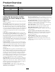
Product Overview Specifications Model Number Net Weight 03480 36 kg (78 lb) 03481 37 kg (80 lb) 03482 40 kg (87 lb) 03483 42 kg (91 lb) Cutting Unit Accessories and Kits (Refer to the Parts Catalog for Part Numbers) Rear Lift Cylinder Kit: Collars assembled on the rear cutting-unit lift-arm cylinders to limit the height of the cutting units. This increases the area for the rear grass baskets.
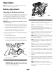
Operation Note: Determine the left and right sides of the machine from the normal operating position. Making Adjustments Adjusting the Bedknife to the Reel Use this procedure to set the bedknife to the reel and to check the condition of the reel and bedknife and their interaction. After completing this procedure, always test the cutting unit performance under your field conditions. You may need to make further adjustments to obtain optimal cutting performance. Figure 9 1. Kickstand 4.
6. Secure the roller bracket and spacers to the underside of the side-plate mounting flanges with the nuts previously removed. 11. From this position (1 click in and shim not passing through) turn the bedbar adjusters clockwise 2 clicks each. Note: Each click turned moves the bedknife 0.018 mm (0.0007 inch). Do not overtighten the adjusting screws. 7. Verify that the bedknife-to-reel contact is correct. Tip the mower to expose the front and rear rollers and the bedknife. 12.
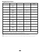
Rear Spacers Height-of-Cut Chart Terms The number of rear spacers determines the aggressiveness of cut for the cutting unit. For a given height of cut, adding spacers below the side-plate mounting flange increases the aggressiveness of the cutting unit. All cutting units on a given machine must be set to the same aggressiveness of cut (number of rear spacers, Part No. 106-3925); otherwise, the after-cut appearance could be negatively affected (Figure 13).
Height-of-Cut Chart HOC Setting Aggressiveness of Cut No. of Rear Spacers No. of Chain Links With Groomer kits installed** 0.64 cm (0.250 inch) Less Normal More 0 0 1 3+ 3+ 3 Y Y - 0.95 cm (0.375 inch ) Less Normal More 0 1 2 4 3 3 Y Y - 1.27 cm (0.500 inch) Less Normal More 0 1 2 4 3+ 3 Y Y Y 1.56 cm (0.625 inch) Less Normal More 1 2 3 4 3 3 Y Y - 1.91 cm (0.750 inch) Less Normal More 2 3 4 3+ 3 3 Y Y - 2.22 cm (0.875 inch) Less Normal More 2 3 4 4 3 3 Y Y - 2.54 cm (1.
Adjusting the Height of Cut Note: For heights of cut greater than 2.5 cm (1 inch) install the High Height-of-Cut Kit. 1. Loosen locknuts securing height-of-cut brackets to cutting-unit side plates (Figure 15). Figure 17 Important: When set properly, the rear and front rollers will contact the gauge bar and the screw will be snug against the bedknife. This ensures that the height of cut is identical at both ends of the bedknife. Figure 15 1. Adjusting screw 3. Height-of-cut bracket 6.
Use the following chart to determine which bedknife is best suited for the desired height of cut. Bedknife/Height-of-Cut Chart Bedknife Bedknife Lip Height Height of Cut EdgeMax® Low HOC (03481 and 03483) 5.6 mm (0.220 inch) 6.4-12.7 mm (0.250-0.500 inch) Low HOC (Optional) 5.6 mm (0.220 inch) 6.4-12.7 mm (0.250-0.500 inch) Extended EdgeMax® Low HOC (Optional) 5.6 mm (0.220 inch) 6.4-12.7 mm (0.250-0.500 inch) Extended Low HOC (Optional) 5.6 mm (0.220 inch) 6.4-12.7 mm (0.250-0.
Checking and Adjusting the Cutting Unit The dual-knob bedknife-to-reel adjustment system incorporated in this cutting unit simplifies the adjustment procedure needed to deliver optimum mowing performance. The precise adjustment possible with the dual-knob/bedbar design gives the necessary control to provide a continual self-sharpening action—thus maintaining sharp cutting edges, ensuring a good quality of cut, and greatly reducing the need for routine back lapping.
Servicing the Bedknife The bedknife service limits are listed in the following charts. Important: Operating the cutting unit with the bedknife below the service limit may result in poor after-cut appearance and reduce the structural integrity of the bedknife for impacts. Bedknife Service Limit Chart Bedknife Bedknife Lip Height * Service Limit * Grind Angles Top/Front Angles EdgeMax® Low HOC (03481 and 03483) 5.6 mm (0.220 inch) 6.4-12.7 mm (0.250-0.500 inch) 10/5 degrees Low HOC (Optional) 5.
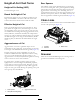
Maintenance Servicing the Bedbar Lubricating the Machine Removing the Bedbar 1. Turn the bedbar adjusting screws counterclockwise to back the bedknife away from the reel (Figure 24). Regularly lubricate the 5 grease fittings of each cutting unit (Figure 23) with No. 2 lithium grease. There are 2 lubrication points on the front roller, 2 on the rear roller, and 1 at the reel-motor spline.
Assembling the Bedbar 1. Install the bedbar, positioning the mounting ears between the washer and the bedbar adjuster. 2. Secure the bedbar to each side plate with the bedbar bolts (nuts on bolts) and the 6 washers. Note: Position a nylon washer on each side of the side-plate boss. Place a steel washer outside each of the nylon washers (Figure 26). 3. Torque bedbar bolts to 37 to 45 N-m (27 to 33 ft-lb).
Servicing the Roller and outer seals to rebuild a roller. The Roller Rebuild Tool Kit includes all the tools and the installation instructions required to rebuild a roller with the roller rebuild kit. Refer to your Parts Catalog or contact your Authorized Distributor for assistance. The Roller Rebuild Kit and the Roller Rebuild Tool Kit (Figure 28) are available for servicing the roller. The Roller Rebuild Kit includes all the bearings, bearing nuts, inner seals, Figure 28 1. Roller Rebuild Kit (Part No.
Declaration of Incorporation The Toro Company, 8111 Lyndale Ave. South, Bloomington, MN, USA declares that the following unit(s) conform(s) to the directives listed, when installed in accordance with the accompanying instructions onto certain Toro models as indicated on the relevant Declarations of Conformity. Model No. Serial No.
International Distributor List Distributor: Agrolanc Kft Asian American Industrial (AAI) B-Ray Corporation Brisa Goods LLC Casco Sales Company Ceres S.A. CSSC Turf Equipment (pvt) Ltd. Cyril Johnston & Co. Cyril Johnston & Co. Fat Dragon Femco S.A. FIVEMANS New-Tech Co., Ltd ForGarder OU G.Y.K. Company Ltd. Geomechaniki of Athens Golf international Turizm Hako Ground and Garden Hako Ground and Garden Hayter Limited (U.K.) Hydroturf Int. Co Dubai Hydroturf Egypt LLC Irrimac Irrigation Products Int'l Pvt Ltd.
Toro General Commercial Product Warranty A Two-Year Limited Warranty Conditions and Products Covered The Toro Company and its affiliate, Toro Warranty Company, pursuant to an agreement between them, jointly warrant your Toro Commercial product (“Product”) to be free from defects in materials or workmanship for two years or 1500 operational hours*, whichever occurs first. This warranty is applicable to all products with the exception of Aerators (refer to separate warranty statements for these products).