Form No. 3397-842 Rev B 18-inch or 22-inch 8-Blade or 11-Blade DPA Cutting Unit Reelmaster® 3550 or 3555 Series Traction Unit Model No. Model No. Model No. Model No. Register at www.Toro.com. Original Instructions (EN) 03485—Serial No. 03486—Serial No. 03487—Serial No. 03488—Serial No.
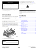
This manual identifies potential hazards and has safety messages identified by the safety-alert symbol (Figure 2), which signals a hazard that may cause serious injury or death if you do not follow the recommended precautions. WARNING CALIFORNIA Proposition 65 Warning This product contains a chemical or chemicals known to the State of California to cause cancer, birth defects, or reproductive harm. Figure 2 1. Safety-alert symbol This product complies with all relevant European directives.
Safety is advisable and required by some local ordinances and insurance regulations. This machine has been designed in accordance with EN ISO 5395:2013 and ANSI B71.4-2012. • Tie back long hair. Do not wear jewelry. • Remove all debris or other objects that might be picked Improper use or maintenance of this equipment can result in injury or death. To reduce the potential for injury or death, comply with the following safety instructions.
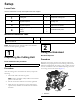
Setup Loose Parts Use the chart below to verify that all parts have been shipped. Procedure Description 1 2 3 4 Use Qty. Cutting unit 1 Inspect the cutting unit. No parts required – Use the kickstand when tipping the cutting unit. No parts required – Adjust the rear shield. Straight grease fitting O-ring Screws 1 1 2 Install the loose parts. Media and Additional Parts Description Parts Catalog Operator's Manual Qty. Use 1 1 Review these materials and save them for future reference.
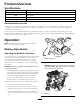
3 Adjusting the Rear Shield No Parts Required Figure 5 Procedure Under most conditions, you can attain the best dispersion when the rear shield is closed (front discharge). When conditions are heavy or wet, you can open the rear shield. 1. Cutting unit 1 5. Cutting unit 5 2. Cutting unit 2 6. Reel motor 3. Cutting unit 3 7. Weight 4.
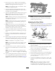
Product Overview Specifications Model Number Net Weight 03485 37 kg (82 lb) 03486 39 kg (85 lb) 03487 42 kg (92 lb) 03488 44 kg (97 lb) Attachments/Accessories A selection of Toro-approved attachments and accessories is available for use with the machine to enhance and expand its capabilities. Contact your Authorized Service Dealer or Distributor or go to www.Toro.
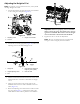
4. Rotate the reel so that a blade crosses the bedknife approximately 25 mm (1 inch) in from the end of the bedknife on the right side of the cutting unit. Note: Put an identifying mark on this blade to make subsequent adjustments easier. 5. Insert the 0.05 mm (0.002 inch) shim between the marked reel blade and the bedknife at the point where the blade crosses the bedknife. 6.
setups cut more grass off by allowing the spinning reel to pull more grass up into the bedknife. the cutting unit on a surface plate and loosening the side-plate mounting bolts (Figure 12). g027270 Figure 12 1. Side-plate mounting bolts Figure 13 8. Adjust and tighten the bolts and torque them to 37 to 45 N-m (27 to 33 ft-lb). 1. Rear spacers 3. Aggressiveness of cut 2.
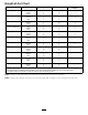
Height-of-Cut Chart HOC Setting Aggressiveness of Cut No. of Rear Spacers No. of Chain Links With Groomer kits installed** 0.64 cm (0.250 inch) Less Normal More 0 0 1 3+ 3+ 3 Y Y - 0.95 cm (0.375 inch ) Less Normal More 0 1 2 4 3 3 Y Y - 1.27 cm (0.500 inch) Less Normal More 0 1 2 4 3+ 3 Y Y Y 1.56 cm (0.625 inch) Less Normal More 1 2 3 4 3 3 Y Y - 1.91 cm (0.750 inch) Less Normal More 2 3 4 3+ 3 3 Y Y - 2.22 cm (0.875 inch) Less Normal More 2 3 4 4 3 3 Y Y - 2.54 cm (1.
Adjusting the Height of Cut Note: For heights of cut greater than 2.5 cm (1 inch) install the High Height-of-Cut Kit. 1. Loosen the locknuts securing the height-of-cut brackets to the cutting-unit side plates (Figure 15). Figure 17 Important: When set properly, the rear and front rollers contact the gauge bar and the screw is snug against the bedknife. This ensures that the height of cut is identical at both ends of the bedknife. Figure 15 1. Adjusting screw 6. Tighten the nuts to secure the adjustment.
Use the following chart to determine which bedknife is best suited for the desired height of cut. Bedknife/Height of Cut Chart Bedknife Part No. Bedknife Lip Height Height of Cut Low HOC (Optional) 121-3167 (18 inch) 110-4084 (22 inch) 5.6 mm (0.220 inch) 6.4 to 12.7 mm (0.250 to 0.500 inch) 5.6 mm (0.220 inch) 6.4 to -12.7 mm (0.250 to 0.500 inch) EdgeMax® Low HOC (Model 03485) (Model 03487) 130-4745 (18 inch) 127-7132 (22 inch) Extended Low HOC (Optional) 120-1640 (22 inch) 5.6 mm (0.
Checking and Adjusting the Cutting Unit Note: Over time, you will need to grind the chamfer (Figure 21), as it is only designed to last 40% of the bedknife life. The dual knob bedknife-to-reel adjustment system incorporated in this cutting unit simplifies the adjustment procedure needed to deliver optimum mowing performance.
Maintenance Relief-Grinding the Reel Lubricating the Machine The reel has a land width of 1.3 to 1.5 mm (0.050 to 0.060 inch) and a 30-degree relief grind. Regularly lubricate the 5 grease fittings of each cutting unit (Figure 22) with No. 2 lithium grease. When the land width gets larger than 3 mm (0.120 inch) wide, do the following: There are 2 lubrication points on the front roller, 2 on the rear roller, and 1 at the reel-motor spline. 1.
Note: This causes the land width to grow slightly. Note: To extend the longevity of the sharpness of the edge of the reel and the bedknife—after grinding the reel and/or the bedknife—check the reel-to-bedknife contact again after cutting 2 fairways, as any burrs will be removed, which may create improper reel-to-bedknife clearance and thus accelerate wear.
Servicing the Bedknife The bedknife service limits are listed in the following chart. Important: Operating the cutting unit with the bedknife below the service limit may result in poor after-cut appearance and reduce the structural integrity of the bedknife for impacts. Bedknife Service Limit Chart Bedknife Part No. Bedknife Lip Height* Service Limit* Low HOC (Optional) 121-3167 (18 inch) 110-4084 (22 inch) 5.6 mm (0.220 inch) 4.8 mm (0.190 inch) 130-4745 (18 inch) 127-7132 (22 inch) 5.6 mm (0.
Servicing the Bedbar Removing the Bedbar 1. Turn the bedbar-adjusting screws counterclockwise to back the bedknife away from the reel (Figure 29). Figure 27 2. Angle indicator 1. Bedknife (vertical) 2. Press the Alt Zero button on the angle indicator. 3. Place the angle-indicator mount on the edge of the bedknife so that the edge of the magnet is mated with the edge of the bedknife (Figure 28).
Assembling the Bedbar 8. Install the bedbar, positioning the mounting ears between the washer and the bedbar adjuster. 1. Install the bedbar, positioning the mounting ears between the washer and the bedbar adjuster. 9. Secure the bedbar to each side plate with the bedbar bolts (nuts on bolts) and 6 washers as follows: 2. Secure the bedbar to each side plate with the bedbar bolts (nuts on bolts) and the 6 washers. A. Position a nylon washer on each side of the side-plate boss.
11 G016355 10 7 9 8 4 6 5 2 3 1 Figure 33 2. Wave washer 4. Apply anti-seize compound here. 5. Flat washer 7. Apply anti-seize compound 10. Compression spring here. 8. Bedbar-adjuster screw 11. Spring-tension nut 3. Flange bushing 6. Locknut 9. Hardened washer 1.
Servicing the Roller nuts, inner seals, and outer seals to rebuild a roller. The Roller Rebuild Tool Kit includes all the tools and the installation instructions required to rebuild a roller with the Roller Rebuild Kit. Refer to your Parts Catalog or contact your distributor for assistance. The Roller Rebuild Kit and the Roller Rebuild Tool Kit (Figure 34) are available for servicing the roller. The Roller Rebuild Kit includes all the bearings, bearing Figure 34 1. Rebuild kit (Part No.114-5430) 6.
Notes: 20
Notes: 21
Declaration of Incorporation The Toro Company, 8111 Lyndale Ave. South, Bloomington, MN, USA declares that the following unit(s) conform(s) to the directives listed, when installed in accordance with the accompanying instructions onto certain Toro models as indicated on the relevant Declarations of Conformity. Model No. Serial No.
International Distributor List Distributor: Agrolanc Kft Asian American Industrial (AAI) B-Ray Corporation Brisa Goods LLC Casco Sales Company Ceres S.A. CSSC Turf Equipment (pvt) Ltd. Cyril Johnston & Co. Cyril Johnston & Co. Fat Dragon Femco S.A. FIVEMANS New-Tech Co., Ltd ForGarder OU G.Y.K. Company Ltd. Geomechaniki of Athens Golf international Turizm Hako Ground and Garden Hako Ground and Garden Hayter Limited (U.K.) Hydroturf Int. Co Dubai Hydroturf Egypt LLC Irrimac Irrigation Products Int'l Pvt Ltd.
The Toro Warranty A Two-Year Limited Warranty Conditions and Products Covered The Toro Company and its affiliate, Toro Warranty Company, pursuant to an agreement between them, jointly warrant your Toro Commercial product (“Product”) to be free from defects in materials or workmanship for two years or 1500 operational hours*, whichever occurs first. This warranty is applicable to all products with the exception of Aerators (refer to separate warranty statements for these products).