Form No. 3420-448 Rev A 18-inch or 22-inch 8-Blade or 11-Blade DPA Cutting Unit Reelmaster® 3550 or 3555 Series Traction Unit Model No. Model No. Model No. Model No. Register at www.Toro.com. Original Instructions (EN) 03485—Serial No. 03486—Serial No. 03487—Serial No. 03488—Serial No.
WARNING Model No. CALIFORNIA Proposition 65 Warning This product contains a chemical or chemicals known to the State of California to cause cancer, birth defects, or reproductive harm. Serial No. This manual identifies potential hazards and has safety messages identified by the safety-alert symbol (Figure 2), which signals a hazard that may cause serious injury or death if you do not follow the recommended precautions. This product complies with all relevant European directives.
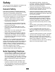
Safety • Wear appropriate clothing, including eye protection; substantial, slip-resistant footwear; long pants, and hearing protection. Tie back long hair and do not wear loose jewelry. This machine has been designed in accordance with EN ISO 5395:2013 and ANSI B71.4-2012. • Inspect the area where the equipment is to be used and remove all objects, such as rocks, toys, and wire, that the machine can throw.
Safety and Instructional Decals Safety decals and instructions are easily visible to the operator and are located near any area of potential danger. Replace any decal that is damaged or missing. decal93-6688 93-6688 1. Warning—read the instructions before servicing or performing maintenance. 2. Cutting hazard of hand or foot—shut off the engine and wait for moving parts to stop.
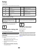
Setup Loose Parts Use the chart below to verify that all parts have been shipped. Procedure Description 1 2 3 4 Use Qty. Cutting unit 1 Inspect the cutting unit. No parts required – Use the kickstand when tipping the cutting unit. No parts required – Adjust the rear shield. Straight grease fitting O-ring Screws 1 1 2 Install the loose parts. Media and Additional Parts Description Qty.
4 Installing the Loose Parts Parts needed for this procedure: g027165 1 Straight grease fitting 1 O-ring 2 Screws Figure 3 Procedure 1. Kickstand Install the grease fitting on the reel-motor side of the cutting unit. Use Figure 5 to determine the position of the reel motors. 3 Adjusting the Rear Shield No Parts Required Procedure g031275 Figure 5 Under most conditions, you can attain the best dispersion when the rear shield is closed (front discharge).
4. Install the O-ring on the reel motor (Figure 7). g031254 Figure 7 1. O-ring 5. Install the reel motor. 6. Grease the side plate until excess grease comes out the grease vent (Figure 6).
Product Overview Specifications Model Number Net Weight 03485 37 kg (82 lb) 03486 39 kg (85 lb) 03487 42 kg (92 lb) 03488 44 kg (97 lb) Attachments/Accessories A selection of Toro-approved attachments and accessories is available for use with the machine to enhance and expand its capabilities. Contact your Authorized Service Dealer or Distributor or go to www.Toro.
Note: This procedure should not be needed on daily adjustments, but should be done after grinding or disassembly. 11. From this position (1 click in and shim not passing through) turn the bedbar adjusters clockwise 2 clicks each. Note: Each click turned moves the bedknife 0.018 mm (0.0007 inch). Do not overtighten the adjusting screws. 12. g027165 Figure 9 1. Kickstand 4.
3. Remove the 2 nuts securing each roller bracket and the spacer to each side-plate mounting flange. 4. Lower the roller and the screws from side-plate mounting flanges and spacers. 5. Place the spacers onto the screws on the roller brackets. 6. Secure the roller bracket and spacers to the underside of the side-plate mounting flanges with the nuts previously removed. 7. setup (aggressiveness of cut, rollers, bedknives, attachments installed, turf-compensation settings, etc.
Chain Links The location at which the lift-arm chain is attached determines the pitch angle of the rear roller (Figure 14). g027264 Figure 14 1. Bottom hole 2. U-backet 3. Lift chain Groomer These are the recommended height-of-cut settings when a groomer kit is installed on the cutting unit.
Height-of-Cut Chart HOC Setting Aggressiveness of Cut No. of Rear Spacers No. of Chain Links With Groomer kits installed** 0.64 cm (0.250 inch) Less Normal More 0 0 1 3+ 3+ 3 Y Y - 0.95 cm (0.375 inch ) Less Normal More 0 1 2 4 3 3 Y Y - 1.27 cm (0.500 inch) Less Normal More 0 1 2 4 3+ 3 Y Y Y 1.56 cm (0.625 inch) Less Normal More 1 2 3 4 3 3 Y Y - 1.91 cm (0.750 inch) Less Normal More 2 3 4 3+ 3 3 Y Y - 2.22 cm (0.875 inch) Less Normal More 2 3 4 4 3 3 Y Y - 2.54 cm (1.
Adjusting the Height of Cut ends of the roller until the entire roller is parallel to the bedknife. Note: For heights of cut greater than 2.5 cm (1 inch) install the High Height-of-Cut Kit. 1. Loosen the locknuts securing the height-of-cut brackets to the cutting-unit side plates (Figure 15). g027266 Figure 17 Important: When set properly, the rear and front rollers contact the gauge bar and the screw is snug against the bedknife.
Use the following chart to determine which bedknife is best suited for the desired height of cut. Bedknife/Height of Cut Chart Bedknife Part No. Bedknife Lip Height Height of Cut Low HOC (Optional) 121-3167 (18 inch) 110-4084 (22 inch) 5.6 mm (0.220 inch) 6.4 to 12.7 mm (0.250 to 0.500 inch) 5.6 mm (0.220 inch) 6.4 to -12.7 mm (0.250 to 0.500 inch) EdgeMax® Low HOC (Model 03485) (Model 03487) 137-0830 (18 inch) 137-0832 (22 inch) Extended Low HOC (Optional) 120-1640 (22 inch) 5.6 mm (0.
Checking and Adjusting the Cutting Unit Note: After extended running, a ridge will eventually develop at both ends of the bedknife. Round off or file these notches flush with the cutting edge of the bedknife to ensure smooth operation. The dual knob bedknife-to-reel adjustment system incorporated in this cutting unit simplifies the adjustment procedure needed to deliver optimum mowing performance.
Maintenance Lubricating the Machine Regularly lubricate the 5 grease fittings of each cutting unit (Figure 22) with No. 2 lithium grease. There are 2 lubrication points on the front roller, 2 on the rear roller, and 1 at the reel-motor spline. Note: Lubricating the cutting units immediately after washing helps purge water out of the bearings and increases bearing life. 1. Wipe each grease fitting with a clean rag. 2.
Servicing the Bedknife The bedknife service limits are listed in the following chart. Important: Operating the cutting unit with the bedknife below the service limit may result in poor after-cut appearance and reduce the structural integrity of the bedknife for impacts. Bedknife Service Limit Chart Bedknife Part No. Bedknife Lip Height* Service Limit* Low HOC (Optional) 121-3167 (18 inch) 110-4084 (22 inch) 5.6 mm (0.220 inch) 4.8 mm (0.190 inch) 137-0830 (18 inch) 137-0832 (22 inch) 5.6 mm (0.
Servicing the Bedbar Removing the Bedbar 1. Turn the bedbar-adjusting screws counterclockwise to back the bedknife away from the reel (Figure 29). g034113 Figure 27 2. Angle indicator 1. Bedknife (vertical) 2. Press the Alt Zero button on the angle indicator. 3. Place the angle-indicator mount on the edge of the bedknife so that the edge of the magnet is mated with the edge of the bedknife (Figure 28).
3. Align the keys on the flange bushings to the slots in the frame and install the bushings (Figure 33). 4. Install a wave washer onto the adjuster shaft and slide the adjuster shaft into the flange bushings in the frame of the cutting unit (Figure 33). 5. Secure the adjuster shaft with a flat washer and a locknut (Figure 33). Torque the locknut to 20 to 27 N∙m (15 to 20 ft-lb). g027176 Figure 31 1. Bedbar bolt 2. Nut 3. Steel washer 4.
g016355 Figure 33 2. Wave washer 4. Apply anti-seize compound here. 5. Flat washer 7. Apply anti-seize compound 10. Compression spring here. 8. Bedbar-adjuster screw 11. Spring-tension nut 3. Flange bushing 6. Locknut 9. Hardened washer 1.
Servicing the Roller nuts, inner seals, and outer seals to rebuild a roller. The Roller Rebuild Tool Kit includes all the tools and the installation instructions required to rebuild a roller with the Roller Rebuild Kit. Refer to your Parts Catalog or contact your distributor for assistance. The Roller Rebuild Kit and the Roller Rebuild Tool Kit (Figure 34) are available for servicing the roller. The Roller Rebuild Kit includes all the bearings, bearing g007790 Figure 34 1. Rebuild kit (Part No.
Declaration of Incorporation The Toro Company, 8111 Lyndale Ave. South, Bloomington, MN, USA declares that the following unit(s) conform(s) to the directives listed, when installed in accordance with the accompanying instructions onto certain Toro models as indicated on the relevant Declarations of Conformity. Model No. Serial No.
European Privacy Notice The Information Toro Collects Toro Warranty Company (Toro) respects your privacy. In order to process your warranty claim and contact you in the event of a product recall, we ask you to share certain personal information with us, either directly or through your local Toro company or dealer. The Toro warranty system is hosted on servers located within the United States where privacy law may not provide the same protection as applies in your country.
The Toro Warranty A Two-Year Limited Warranty Conditions and Products Covered The Toro Company and its affiliate, Toro Warranty Company, pursuant to an agreement between them, jointly warrant your Toro Commercial product (“Product”) to be free from defects in materials or workmanship for two years or 1500 operational hours*, whichever occurs first. This warranty is applicable to all products with the exception of Aerators (refer to separate warranty statements for these products).