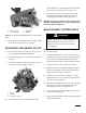
FORM NO. 3318-294 GB Rev A MODEL NO. 03505—60001 & UP MODEL NO. 03508—60001 & UP ® OPERATOR’S MANUAL REELMASTER® 5100 CUTTING UNIT The TORO COMPANY—1991, Rev.
Table of Contents Page No. Page No. SPECIFICATIONS 2 BACKLAPPING CUTTING UNITS 5 ADJUSTING THE CUTTING UNIT 3 LUBRICATION 6 Adjusting Bedknife to Reel 3 MAINTENANCE 6 Adjusting Shield Height 3 Removing Bedknife For Grinding 7 Adjusting Top Bar 4 Preparing Reel for Grinding 7 Leveling Front Roller to Reel 4 Servicing and Adjusting Reel Bearings 7 Adjusting Height of Cut 5 Removal of Reel Assembly 7 Specifications REEL CONSTRUCTION: 5 or 8 blades riveted to 5 cast spiders.
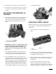
. Insure that all nuts and bolts are securely fastened. 4. Check the level of the front roller to the reel; refer to the section on Leveling the Front Roller Assembly to the Reel. reel sharpening manual). ADJUSTING THE BEDKNIFE TO THE REEL 1. First, loosen the bottom screw on each side of the cutting unit (Fig. 1), then tighten the top adjustment screw on each side of the cutting unit. This adjustment will position the bedknife closer to the reel blades.
recutting . To open the rear shield: 1. Loosen the locking bolt on the side of the cutting unit (Fig. 4). Figure 5 1. 2. Top bar Bar mounting screws LEVELING THE FRONT ROLLER TO THE REEL Figure 4 1. 1. Adjust the rear roller assembly to the lowest height-of cut; refer to the section on Adjusting the Height of Cut. Do not tighten nuts securing height-of-cut brackets at this time. 2. Place a 1⁄4 inch or thicker plate under the reel blades and against the cutting edge of the bedknife (Fig. 6).
desired height of cut, making this measurement from the bar face to the underside of the screw head. 5. Place the bar across the front and rear rollers and adjust the tap bolt until the underside of the screw head engages the bedknife cutting edge (Fig. 7). IMPORTANT: Do procedure No. 4 on each end of the bedknife. Tighten height of cut adjustment locknuts on both ends. Recheck adjustment. Figure 6 1. 2. Rear roller bracket 1/4 inch steel plate 3. 4.
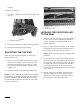
CAUTION Be careful when lapping the reel because contact with the reel or other moving parts can result in personal injury. 8. 9. To make an adjustment to the cutting units while backlapping, turn the reels OFF by moving the Lower Mow/Raise lever REARWARD, Move the Enable/ Disable switch to DISABLE and turn the engine OFF. After adjustments have been completed, repeat steps 3–7. Figure 8 2. A. Hydraulic motor end: apply grease until pressure is felt against the handle.
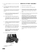
REMOVING THE BEDKNIFE FOR GRINDING The rear roller assembly must be removed to remove the bedknife assembly for sharpening. To remove the rear roller, proceed as follows: 1. 2. Remove the capscrew and nut anchoring the rear roller height-of-cut bracket to the side plate on both ends of the cutting unit (Fig. 10). Loosen set screws securing the rear roller shaft to the height-of-cut brackets.
1. First, adjust the bedknife so it is not in contact with the reel. 2. The rolling torque required to turn the reel should be 4 to 7 inch pounds. This should be measured with a torque wrench. If the rolling torque of the reel is not per specification or end play of reel exists, adjust the reel bearing as follows: A. Remove the mounting nuts from the counterbalance end cap and remove end cap from the mounting studs (Fig. 10). B. Using a large socket wrench, remove the reel bearing adjustment nut.