FORM NO. C MODEL NO. 03505 — 20556 thru OPERATOR’S MODEL N050 thi . r 50001 & UP MANUAL steelmaker@ 5100 CUTTING UNIT J ©The TOR COMPANY — 1991, Rev.
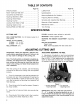
TABLE OF CONTENTS SPECIFICATIONS v liar s KNOW YOUR CUTTING UNIT .. ADJUSTING CUTTING UNIT .. Adjusting Bed knife to Reel Adjusting Shield Height .. .. Adjusting Top Bar Leveling Front Rifler to Reel Adjusting Height-of-Cut BACKSLAPPING CUTTING UNIT . Page No. LUBRICATION 6 MAINTENANCE clinic vy 6 Removing Bed knife For Grinding 8 Preparing Reel for Grinding oviducts 8 Servicing and Adjusting Reel Bearings 6 Removal of Reel Assembly . . 6 Maintenance Chart . Toto Promise .. .
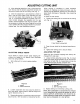
ADJUSTING CUTTING UNIT 2. After adjusting bed knife to reel, make sure that both the top and the bottom adjustment screws are secured on both ends of the cutting unit (Fig. 1}. 3. Alter the adjustment is accomplished, check to see if reel can pinch paper when inserted from the front and cut paper when inserted at a right angle (Fig. 2}. & should be possible to cut paper with minimum contact between the bed knife and the reel blades.
ADJUSTING CUTTING UNIT LEVELING FRONT ROLLER TO REEL 1. Adjust rear roller assembly to lowest featherweight, refer to section on Adjusting Height of Cut. Do not tighten nuts securing height of cut brackets at this time, 2. Place a 1/4 inch or thicker plate under the reel blades and against the cutting edge of the bed knife {Fig. 8). Rear roller should not contact surface. NOTE: Be sure the piste covers the full length of reel blades. 3.
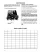
BACKSLAPPING CUTTING UNITS 4. Set both reel speed controls to position 11. Select either front or rear on backpack switch to determine which units to back lap. 8. Move enable / disable switch to enable position. Move lower mow / raise lever forward to start backslapping operation on designated reels, 6. For the cutting units being back lapped, move the reel speed control to position 1. 7. Apply lapping compound with long handled brush supplied with machine.
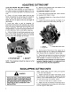
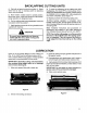
MAINTENANCE IMPORTANT: Reel motors must be removed before removing the cutting units to prevent hose damage due to twisting, bending, and kinking. REMOVING BED KNIFE FOR GRINDING The rear rosier assembly must be removed in order to remove the bed knife assembly for sharpening. To remove the rear roller, proceed as follows: 1. Remove cap screw and nut anchoring the rear roller bracket to the side plate on both ends of the cutting unit (Fig. 10). 2.
MAINTENANCE 4. Using an appropriate torque wrench, check the rolling torque of the reel. The rolling torque of the reel should be 410 7 in.lb. Check to make sure no end play exists and reel spins freely. 5. Reinstall the counterbalance end cap. Figure 11 1. Rose Bearing Housing 2. Splint Nut REMOVAL OF REEL ASSEMBLY IMPORTANT: Before removing cutting unit, remove rel motors to prevent damaging hydraulic hoses, 1. Remove the front roller assembly. 2. Remove counterbalance End Cap (Fig. 10). 3.
The Torn Premise A ONE YEAR LIMITED WARRANTY The Toto Company promises to repair your TOR Product if defective in materials or workmanship. The following time periods from the date of purchase apply: Commercial Products Year The costs of parts and labor are included, but the customer pays the transportation costs on walk rotary mowers with cutting welt widths of less than 25°. i you feel your TOR product is defective and wish to rely on The Toto Promise, the following procedure is recommended: 1.