
Operator's Manual


8
1
1
1
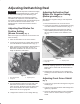
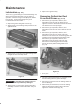
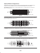
Figure 13
1. Index hole
5. After assembly of the spacers and blades, apply
Blue Loctite #242 to the 1–1/8 in. nut and tighten
to 80 –100 ft–lb.
6. Check positive or negative reel setting and
readjust, if necessary.
7. The spline nut, on driven end, must be torqued to
40–60 ft–lb.
Reversing Dull Dethatcher
Blades
When dethatcher blades become dull grinding is not
required. The dethatcher blades can be disassembled
from the reel, reversed 180_, and reassembled.
Grinding of the blades is only required when both
sides of the reel have become dull or rounded.
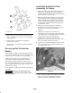
Reassemble dethatcher blades by inverting them
180_ and reassembling them onto the hex shaft. This
will be evident by all the sharp edges of the blades in
the direction of rotation.
Check positive or negative reel setting and readjust, if
necessary.
Important Make sure the sharp edge of the
blades are in the direction of the rotation of the
dethatching unit.
Assemble Dethatcher Reel
Assembly To Frame
1. Slide the reel bearings onto the reel shaft with the
locking collars facing inward and not tightened.
Orientate the grease fittings on the bearings facing
up and forward on the reel frame.
2. After reel shaft assembly has been placed into the
frame apply blue loctite #242 unto (6) capscrews
before assembly onto (2) outside bearing plates.
Install (2) plastic bearing debris seals into opening
on side frame before attaching bearing plates to
the dethatcher frame.
3. Procure reel motor assembly (75–1400) and
assemble reel motor into bearing plate. This is to
be used as an assembly tool for bearing
alignment.
4. Tighten the (3) capscrews, washers, and
lockwashers to 170–220 in–lbs on the driven side
of the dethatcher reel assembly with the reel motor
acting as pilot for the bearing assembly.
5. Tighten the (3) capscrews, washers, and
lockwashers to 170–220 in–lbs on the other end of
the reel assembly. Remove reel motor.
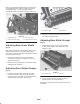
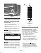
6. Position the reel shaft assembly so that the spline
nut is .50 inward from the outside surface of the
bearing plate (Fig. 14)
Figure 14
7. Use a drive pin and hammer to tighten the locking
collars on the reel shaft bearings. Tighten in
direction of rotation. Tighten setscrews (2).