
Installation Instructions

1
All Rights Reserved
Printed in the USA
W 2006 by The Toro Company
8111 Lyndale Avenue South
Bloomington, MN 55420-1196
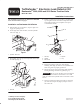
TurfDefendert Electronic Leak Detector Kit
Reelmaster
)
5000, 6000 and 5010 Series Traction Units
Model No. 03521
Form No. 3356–586 Rev A
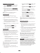
Installation Instructions
The Installation Instructions for Reelmaster 5000/6000
Series Traction Units is on page 2.
Installation on Reelmaster 5010 Series
1. Park machine on a level surface, stop the engine and
engage the parking brake.
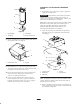
2. On the right side of the machine, raise the hydraulic
tank cover (Fig. 1).
1
Figure 1
1. Hydraulic tank cover
3. Thoroughly clean the top of the hydraulic tank around
the tank cap (Fig. 2).
1
Figure 2
1. Tank cap
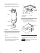
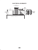
4. Remove (6) flange head screws (Fig. 3) securing tank
cap and gasket to tank and remove components from
tank. Retain the filter screen, dipstick and cap for
re–installation with kit.
1
2
3
4
5
Figure 3
1. Tank cap
2. Gasket
3. Filter screen
4. Dipstick
5. Cap
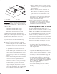
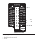
5. Position new flange gasket onto tank aligning
mounting holes (Fig. 4). Holes are not symmetrical so
make sure gasket is properly positioned.
6. Insert leak detector into tank opening while aligning
housing mounting with holes in gasket (Fig. 4).
Important Be sure to use the filter screen and dipstick
previously removed from the tank. Failure to do so will
result in an inaccurate hydraulic oil level and lead to false
detects.
7. Secure leak detector housing and gasket to tank with
(6) socket head capscrews (Fig. 4). Torque screws to
100–125 in–lb.