Form No.
Contents Page Safety . . . . . . . . . . . . . . . . . . . . . . . . . . . . . . . . . . . . . Safe Operating Practices . . . . . . . . . . . . . . . . . . . Safety and Instruction Decals . . . . . . . . . . . . . . . Specifications . . . . . . . . . . . . . . . . . . . . . . . . . . . . . . . Set–Up . . . . . . . . . . . . . . . . . . . . . . . . . . . . . . . . . . . . Loose Parts . . . . . . . . . . . . . . . . . . . . . . . . . . . . . . Inspection . . . . . . . . . . . . . . . . . . . . . . . . . . . .
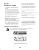
• Remove all debris or other objects that might be picked up and thrown by the cutting unit reel blades. Keep all bystanders away from the mowing area. Safety Safe Operating Practices • If the cutting blades strike a solid object or the cutting unit vibrates abnormally, stop and shut the engine off. Check cutting unit for damaged parts. Repair any damage before restarting and operating the cutting unit.
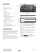
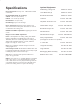
Optional Equipment: Specifications Reel Construction: Fairway reels. 5 & 8 blades welded construction. Recommended Height–of–Cut Range: 5 Blade – 5/8” to 1” (13–25 mm) 8 Blade – 1/4” to 5/8” (6–16 mm) Dethatching Cutting Unit Model No. 03516 Grass Basket Kit (5) Model No. 03532 Rear Roller Brush Kit Model No. 03533 Comb kit Part No. 104–3385 Adjustable Front H.O.C kit Part No. 104–8205 Reel Diameter: 5 in (127 mm) Reel Bearings: Taper roller bearings.
Set–Up Note: Determine the left and right sides of the machine from the normal operating position. Loose Parts Note: Use the chart below to verify all parts have been shipped. DESCRIPTION QTY. USE Decal 1 Apply over existing decal for CE Operator’s Manual 1 Read before operating machine. Parts Catalog 1 Use for ordering replacement parts. Registration Card 1 Fill out and return to Toro. Inspection After the cutting unit is unboxed, inspect the following: 1 1.
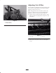
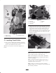
Adjusting Cut–Off Bar The Cut–Off bar is designed to keep the gap between the reel and the Cut–Off minimal to insure grass clippings discharge cleanly from reel area. Note: The gap between the Cut–Off bar and reel will increase as: 1) the reel wears, 2) reel is sharpened by grinding, or 3) if the front grass shield is adjusted. 1 1. Loosen screws securing Cut–Off bar (Fig. 4). Insert 0.060” (2 mm) feeler gauge between top of reel and Cut–Off bar. Figure 3 1.
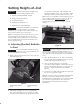
Setting Height–of–Cut on each side of cutting unit. This adjustment will position the bedknife closer to the reel blades. Adjust until light contact is heard on both ends of the reels. Important To insure proper setting of height-of-cut, these procedures must be followed in this order: A. Adjusting (Parallel) Bedknife To Reel Note: Correct reel to bedknife contact should not increase the reel rolling torque more than 3 in–lbs.
B. Setting Cutting Unit Attitude The front brackets have 3 fixed positions for setting cutting unit attitude within the same height–of–cut range (Fig 7). Each change in position changes the cutting unit attitude by 3 degrees. The positions are: Important Cutting unit “attitude” has a significant impact on the performance of the cutting unit. Attitude refers to the angle of the bedknife relative to the ground (Fig. 7).
Checking/Adjusting the Cutting Unit Attitude 2. Using a two-screw gauge bar, Toro Part No. 98-1852, set the height of cut screw to the desired height-of-cut. 3. Place the gauge bar across the front and rear rollers. The height of cut screw head needs to fit snugly over the edge of the bedknife while the gauge bar contacts the rollers (Fig. 10). For setting consistent cutting unit attitude, Toro strongly recommends using a two-screw gauge bar, Toro part no. 98-1852 (Fig. 8).
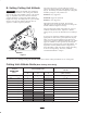
3 Decreases Attitude Increases Attitude 1 2 3 2 4 5 Figure 12 1. Rear roller 2. 1/2 in. steel plate 3. Reel blades 1 4. Bedknife 5. Gap 2. Level front roller to reel by loosening the 4 capscrews holding the front roller brackets and rotating the front roller until it contacts the surface that the plate is on. Tighten the capscrews and make sure that the roller has not changed position. To prevent moving the roller bracket when tightening (Fig. 13), hold the nut while tightening capscrew.
D. Adjusting the Height of Cut The Turf Compensation Spring also transfers weight from the front to rear roller. This helps to reduce a wave pattern in the turf, also known as bobbing. 1. Rotate the cutting unit vertical and place the gauge bar across front and rear rollers (Fig. 14). Important Make spring adjustments with cutting unit mounted to traction unit and lowered to shop floor. Refer to Traction Unit Operator’s Manual for mounting instructions. 2.
Maintenance Note: Do not make lead–in chamfer too large as it may cause turf tufting. Cutting Unit Daily Adjustments Important The reel motors must be removed before removing the cutting units to prevent hose damage due to twisting, bending, and kinking. Prior to mowing each day, or as required, each cutting unit must be checked to verify proper bedknife–to–reel contact. This must be performed even though quality of cut is acceptable. Lubrication There are 6 grease fittings on each cutting unit (Fig.
1. Position the machine on a clean, level surface. Lower the cutting units, stop the engine, engage the parking brakes, move enable/disable switch to disable position, and remove the key from the ignition switch. Note: For a better cutting edge, run a file across the front face of the bedknife when the lapping operation is completed. This will remove any burrs or rough edges that may have built up on the cutting edge. 2. Unlock and raise the seat to expose the controls.
Removing the Reel Assembly B. Using a large socket wrench, remove the reel bearing adjustment nut (Fig. 19). Tap on the head of the hex head bolt on the end of the reel shaft, with a small hammer, until end play of the reel can be felt. Important Before removing the cutting unit, remove the reel motors to prevent damage to the hydraulic hoses. 1. Remove the front roller assembly. 2. Remove the counterbalance weight (Fig. 18). 3.
The Toro General Commercial Products Warranty A Two-Year Limited Warranty Conditions and Products Covered The Toro Company and its affiliate, Toro Warranty Company, pursuant to an agreement between them, jointly warrant your 1996 or newer Toro Commercial Product (“Product”) purchased after January 1, 1997, to be free from defects in materials or workmanship for two years or 1500 operational hours*, whichever occurs first.