
Operator's Manual


10
1
2
3
Decreases
Attitude
Increases
Attitude
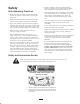
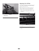
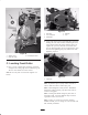
Figure 11
1. Attitude screw
2. Gauge bar angle
3. Front height of cut kit
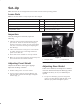
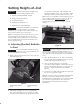
C. Leveling Front Roller
1. Place a 1/2 in. or thicker plate under the reel blades
and against the cutting edge of the bedknife (Fig. 12).
The rear roller should not contact surface.
Note: Be sure the plate covers the full length of reel
blades.
1
2
3
4
5
Figure 12
1. Rear roller
2. 1/2 in. steel plate
3. Reel blades
4. Bedknife
5. Gap
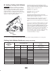
2. Level front roller to reel by loosening the 4 capscrews
holding the front roller brackets and rotating the front
roller until it contacts the surface that the plate is on.
Tighten the capscrews and make sure that the roller
has not changed position. To prevent moving the roller
bracket when tightening (Fig. 13), hold the nut while
tightening capscrew.
1
Figure 13
1. Capscrews
Note: Try to slide a piece of paper under each end of
roller to make sure there is contact (Fig. 13).
Note: If Front Height of Cut kit, Part No. 104–8205 is
installed on cutting unit (Fig. 11), adjust front roller to
contact leveling plate.
Note: If cutting unit attitude changes by more than 1
from side to side, reel and/or bedknife may need to be
reground to remove uneven wear.
Note: If rollers are parallel to reel before changing
bedknife attitude, you can change one roller at a time and
still maintain parallelism.