Form No. 3353–145 Rev C Reelmaster 5500–D 2 and 4 Wheel Drive Traction Units Model No. 03550—250000001 and Up Model No.
Bleeding the Fuel System . . . . . . . . . . . . . . . . . . . . Setting the Reel Speed . . . . . . . . . . . . . . . . . . . . . . Adjusting the Rear Lift Arm Counterbalance . . . . Towing the Traction Unit . . . . . . . . . . . . . . . . . . . . Diagnostic Light . . . . . . . . . . . . . . . . . . . . . . . . . . . Diagnostic ACE Display . . . . . . . . . . . . . . . . . . . . Checking the Interlock Switches . . . . . . . . . . . . . . Hydraulic Valve Solenoid Functions . . . . . . . . . . .
Introduction This manual uses two other words to highlight information. Important calls attention to special mechanical information and Note: emphasizes general information worthy of special attention. Read this manual carefully to learn how to operate and maintain your product properly. The information in this manual can help you and others avoid injury and product damage. Although Toro designs and produces safe products, you are responsible for operating the product properly and safely.
• being driven too fast; • Before attempting to start the engine, disengage all blade attachment clutches, shift into neutral, and engage the parking brake. • inadequate braking; • the type of machine is unsuitable for its task; • Remember there is no such thing as a safe slope. Travel on grass slopes requires particular care.
• Be careful during adjustment of the machine to prevent entrapment of the fingers between moving blades and fixed parts of the machine. • Stop the engine and disengage drive to attachment – before refuelling; – before removing the grass catcher/catchers; • On multi-cylinder/multi-reel machines, take care as rotating one cylinder/reel can cause other cylinders/reels to rotate. – before making height adjustment unless adjustment can be made from the operator’s position.
Maintenance and Storage • Do not operate the machine while wearing tennis shoes or sneakers. • Make sure all hydraulic line connectors are tight and all hydraulic hoses and lines are in good condition before applying pressure to the system. • Wearing safety shoes and long pants is advisable and required by some local ordinances and insurance regulations. • Keep your body and hands away from pin hole leaks or nozzles that eject hydraulic fluid under high pressure.
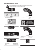
Safety and Instruction Decals Safety decals and instructions are easily visible to the operator and are located near any area of potential danger. Replace any decal that is damaged or lost. 93-6680 93-6699 93-6689 1. Machine speed 2. Slow 1. Warning—do not carry passengers. 3. Continuous variable setting 4. Fast 93-6696 1. Stored energy hazard—read the Operator’s Manual. 104-2052 93-6686 1. Hydraulic oil 2. Read the Operator’s Manual. 105-7506 93-6687 1. Read the Operator’s Manual 2.
104-9296 1. Read the Operator’s Manual. 2. Lower and engage the reels. 3. Raise and disengage the reels. 4. Fast 5. Slow 6. Enable the reels 7. Disable and raise the reels 8. Disable the reels 9. On 10. Off 11. Headlights 104-9294 1. Read the Operator’s Manual. 2. Do not tow the machine. 3. Warning—read the Operator’s Manual. 4. Cutting hazard of hand or foot—stay away from moving parts. 7. Warning—use a roll over protection system and wear the seat belt. 5.
104-9295 Replaces 104–9294 for CE 1. Read the Operator’s Manual. 2. Do not tow the machine. 3. Warning—read the Operator’s Manual. 4. Cutting hazard of hand or foot—stay away from moving parts. 7. Warning—use a roll over protection system and wear the seat belt. 5. Warning—keep bystanders a safe distance from the machine. 6. Warning—lock the parking brake, stop the engine, and remove the ignition key before leaving the machine. 107-8841 9 8.
93-6691 1. Read the Operator’s Manual. 93-6693 1. Crushing hazard of hand—wait for moving parts to stop. 93-6692 1. Read the Operator’s Manual—do not prime or use starting fluid. 94-6767 1. Read the Operator’s Manual. 2. Headlights 3. Engine-start 93-8060 1. Warning—read the Operator’s Manual. 2. Cutting hazard of and or foot—wait for moving parts to stop. 3. For backlapping, set the parking brake and move the throttle lever to Slow (do not change the engine speed while the reels are running).
98-9335 1. Cutting/dismemberment hazard, fan—stay away from moving parts. 93-1263 1. Read the Operator’s Manual. 2. To lock the parking brake, secure the brake pedals with the locking pin, press the brake pedals, and pull out the parking brake knob. 3. To unlock the parking brake, press the brake pedal. 4. Reel failure/malfunction Battery Symbols Some or all of these symbols are on your battery. 1. Explosion hazard 2. No fire, open flames, or smoking. 3. Caustic liquid/chemical burn hazard 4.
General Specifications Engine Main frame Cooling system Fuel system Traction system Ground speed Kubota three cylinder, 4 cycle, liquid cooled, turbo diesel engine. 35 hp @ 3000 rpm. Governed to 3200 rpm. 68–1/2 cubic inch (1123 cc) displacement. Heavy duty, 3-stage, remote mounted air cleaner. High water temperature shutdown switch. All welded formed steel frame, includes tie-down loops Radiator capacity is approximately 240 ounces (9.4 l) of 50/50 mixture of ethylene glycol anti–freeze.
Measurements Optional Equipment Width-of-cut 100 inch (254 cm) Overall width 5 Blade Cutting Unit (7 inch) Model No. 03860 7 Blade Cutting Unit (7 inch) Model No. 03861 Transport 88 inch (224 cm) 11 Blade Cutting Unit (7 inch) Model No. 03862 Outside of front tires 87 inch (221 cm) Dethatching Cutting Unit Model No. 03871 Grass Basket Kit Model No. 03882 Arm Rest Kit Model No. 30707 4 Wheel Drive Kit (For use with model 03550 only) Turf DefenderT Electronic Leak Detector Model No.
Setup Note: Determine the left and right sides of the machine from the normal operating position. Note: Use this chart as a checklist to ensure that all parts necessary for assembly have been received. Without these parts, total set-up cannot be completed. Some parts may have already been assembled at the factory. Description Qty.
Connecting the Battery Warning CALIFORNIA Proposition 65 Warning 2 Battery posts, terminals, and related accessories contain lead and lead compounds, chemicals known to the State of California to cause cancer and reproductive harm. Wash hands after handling. 1 Figure 2 Warning 1. Positive battery cable Battery terminals or metal tools could short against metal tractor components causing sparks. Sparks can cause the battery gasses to explode, resulting in personal injury. 2.
Mounting the Hood Latch Replacing the Floor Panel Fastener (Required for CE) 1. Remove plug from hole in left front corner of hood (Fig. 3). 1. Remove fastener securing left front corner of floor panel to frame (Fig. 5). 2. Open the hood. 2. Replace with a flange head capscrew (5/16 x 5/8 inch) supplied in loose parts (Fig. 5). 1 Figure 3 1. Hood plug 1 3. Mount locking latch to hood with lock washer and nut. Position switch with latch toward front of machine (Fig. 4). 4.
Motor Weight #4 Weight Motor Weight #1 Motor Weight Motor 5 #5 Weight #2 Motor #3 Figure 6 3 Note: Counter weight mounting capscrews are shipped installed on the right bearing housing of the cutting units. The capscrews on left bearing housing are to be used for securing the hydraulic motor. 1. Remove cutting units from cartons. Assemble and adjust per Cutting Unit Operator’s Manual. 2 2. Remove protective plugs from each end of cutting unit. 4 1 Figure 8 3.
Important Make spring adjustments with cutting unit is mounted to traction unit and lowered to shop floor. Refer to Traction Unit Operator’s Manual for mounting instructions. 1 3 2 1. Tighten lock nut on rear of spring rod until the gap C between rear of spring bracket and front of washer is 1 inch (26 mm) (Fig. 11). 2. Tighten hex nuts on front end of spring rod until the compressed length A of spring is 8 inches (203 mm) (Fig. 11).
• Loosen the carriage bolt nut securing the lift arm switch bracket to the #4 lift arm (left front) (Fig. 12). 3 Note: Additional holes are provided to further adjust, if required. Rear Ballast 1 Model 03550 (2 Wheel Drive) complies with the CEN standard EN 836:1997, ISO standard 5395:1990 and the ANSI B71.4–1999 Standard when 100 lbs. (45 kg) of calcium chloride ballast is added to rear wheels and rear weight kit (Part No. 104–1478) is installed.
Before Operating 3. If oil is below full mark, remove fill cap and add oil until level reaches full mark on dipstick (Fig. 14). Do not over fill. Note: Determine the left and right sides of the machine from the normal operating position. 4. Install oil fill cap and close hood. Checking the Cooling System Warning Clean debris off screen, oil cooler and front of radiator daily, more often if conditions are extremely dusty and dirty. Refer to Servicing the Engine Cooling System, page 38.
Filling the Fuel Tank 1 Danger Under certain conditions, diesel fuel and fuel vapors are highly flammable and explosive. A fire or explosion from fuel can burn you and others and can cause property damage. Figure 17 1. Transmission dipstick cap • Use a funnel and fill the fuel tank outdoors, in an open area, when the engine is off and is cold. Wipe up any fuel that spills. • Do not fill the fuel tank completely full. Add fuel to the fuel tank until the level is 1 in.
1. Position machine on a level surface, lower the cutting units and stop the engine. 2 2. Clean area around filler neck and cap of hydraulic tank. Remove cap from filler neck (Fig. 18). 1 1 1 Figure 19 Figure 18 1. Check plug 2. Fill plug 1. Hydraulic tank cap 3. Remove dipstick from filler neck and wipe it with a clean rag. Insert dipstick into filler neck; then remove it and check level of fluid. Fluid level should be within 1/4 inch (6 mm) of mark on dipstick. 4.
Warning Failure to maintain proper torque of the wheel nuts could result in personal injury. Torque the front wheel nuts and rear wheel bolts to 75–80 ft.-lb. after 1–4 hours of operation and again after 10 hours of operation. Torque every 250 hours thereafter. 1 Figure 22 1. Traction pedal Operation Brake Pedals Note: Determine the left and right sides of the machine from the normal operating position.
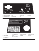
Key Switch Glow Plug Indicator Light Three positions: Off, On/Preheat and Start (Fig. 23). When lit, indicates glow plugs are on (Fig. 24). Speedometer Charge Indicator Indicates ground speed at which machine is traveling (Fig. 23). Illuminates when system charging circuit malfunctions (Fig. 24). Lower Mow/Raise Control Lever Throttle Control The lever raises and lowers the cutting units and also starts and stops the reels (Fig. 24).
Hour Meter (Located under control panel) shows total hours that machine has been operated. Warning 1 Before servicing or making adjustments to the machine, stop the engine and remove the key from the switch. Lower the cutting units to the ground. Figure 26 1. Fuel injection pump bleed screw Starting and Stopping 3. Turn key in ignition switch to the on position. Electric fuel pump will begin operation, thereby forcing air out around air bleed screw.
2. Choose the desired ground speed best suited for conditions. 2 3. Using the appropriate graph (See figure 27) for 5, 7 or 11 blade cutting units, determine the proper reel speed setting. 1 1 2 Figure 28 1. Backlap knobs 2. Reel speed control 5. Operate the machine for several days, then examine the cut to ensure satisfaction with the quality of cut.
Warning 1 Springs are under tension, use caution when adjusting. Figure 30 2 1. Drive shaft 3 1 Important If drive shaft is not removed before towing, the transmission input shaft will not be able to rotate, thus not allowing the transmission to maintain its internal lubrication. Severe damage to the hydrostatic transmission will occur. Figure 29 1. Counterbalance spring 2. Spring bolt 3. Adjustment locations 2. Attach a suitable chain, strap or cable to the center of the front frame member (Fig.
Diagnostic Light the machine as desired, each of the input switches, output solenoids and relays must be connected and functioning properly. The Diagnostic ACE display is a tool to help the user verify correct electrical functions of the machine. The RM 5500–D is equipped with a diagnostic light which indicates if the electronic controller is functioning correctly. The green diagnostic light is located under the control panel, next to the fuse block.
3. Connect the Diagnostic ACE display connector to the harness connector. Make sure correct overlay decal is positioned on Diagnostic ACE display. 2. Open control panel cover. Locate wire harness and connectors near controller. Carefully unplug loopback connector from harness connector. 4. Turn the key switch to the on position, but do not start machine. 3. Connect the Diagnostic ACE connector to the harness connector. Make sure correct overlay decal is positioned on Diagnostic ACE. 1 4.
Running the Mower ACE, disconnect it from the machine and reconnect loopback connector to harness connector. Machine will not operate without loopback connector installed on harness. Store the Diagnostic ACE in dry, secure location in shop, not on machine. Start engine and move throttle to fast so engine is running at maximum speed. Move the enable/disable switch to enable and use the lower mow/raise lever to control the cutting units (front cutting units are timed to lower before the rear cutting units).
Maintenance Note: Determine the left and right sides of the machine from the normal operating position. Recommended Maintenance Schedule Maintenance Service Interval Maintenance Procedure Check the fan and alternator belt tension. Torque the wheel lug nuts. Change the transmission fluid. Replace the transmission filter. After first 10 hours • • • • After first 50 hours • Change the engine oil and filter. • Check the engine RPM (idle and full throttle). • Torque the head and adjust valves.
Lubricating the Mower Warning Before servicing or making adjustments to the machine, stop the engine and remove the key from the switch. Lower the cutting units to the ground. Greasing the Bearing and Bushings The machine has grease fittings that must be lubricated regularly with No. 2 General Purpose Lithium Base Grease. If machine is operated under normal conditions, lubricate all bearings and bushings after every 50 hours of operation.
Figure 39 Figure 42 Figure 40 Figure 43 Figure 41 33
Service Interval Chart Figure 44 34
Daily Maintenance Checklist Duplicate this page for routine use. For the week of: Maintenance Check Item Mon. Tues. Wed. Thurs. Fri. Sat. Sun.
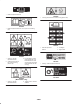
1. Remove thumb screw, separate cover from precleaner bowl. 2 1 1 3 Figure 46 1. Filter element Figure 45 1. Air cleaner indicator 2. Pre cleaner bowl 3. Dust cup 6. Inspect new filter for shipping damage. Check sealing end of filter. Do not install a damaged filter. 7. Insert new filter properly into air cleaner body. Make sure filter is sealed properly by applying pressure to outer rim of filter when installing. Do not press on flexible center of filter. 2. Empty precleaner bowl and wipe clean. 3.
Servicing the Fuel Filter / Water Separator Drain water or other contaminants from fuel filter / water separator (Fig. 49) daily. 1. Locate fuel filter, under hood, and place a clean container under it. 2. Loosen drain plug on bottom of filter canister. Tighten plug after draining. 1 Figure 47 1. Engine oil drain plug 2. Remove the engine oil filter (Fig. 48). Apply a light coat of clean oil to the new filter seal before screwing it on. Do not over–tighten. 1 2 Figure 49 1.
3. Turn key in key switch to start position and watch fuel flow around connector. Engine will crank. Turn key to off position when solid flow is observed. 2 4. Tighten pipe connector securely. 2 5. Repeat steps on remaining nozzles. Servicing the Engine Cooling System 1 Figure 50 1. Fuel filter Removing Debris 2. Hose clamp Remove debris from screen, oil coolers and radiator daily, clean more frequently in dirty conditions. Bleeding Air from the Injectors 1. Turn engine off and raise hood.
2 1 2 1 Figure 54 3 1. Alternator belt 2. Brace 3. Loosen bolt securing brace to engine and bolt securing alternator to brace. 4. Insert pry bar between alternator and engine and pry out on alternator. 5. When proper tension is achieved, tighten alternator and brace bolts to secure adjustment. Figure 53 1. Reel oil cooler 2. Radiator 3. Transmission oil cooler Servicing the Cooling Fan Belt 1. Loosen lock nut on belt tensioner lever. Servicing the Engine Belts 2. Apply 5–10 lb.
Adjusting the Throttle 1 1. Position throttle lever forward so it stops against seat base slot. 2. Loosen the throttle cable connector on the lever arm at the injection pump. 3. Hold the injection pump lever arm against the high idle stop and tighten the cable connector. Note: When tightened, the cable connector must be free to swivel. 4.
Using the Hydraulic System Test Ports The test ports are used to test pressure in the hydraulic circuits. Contact your local Toro distributor for assistance. 1 1. Test Port #1 is used to assist in trouble shooting the hydraulic circuit for the front cutting units and lift cylinders. Figure 58 2 1. Hydraulic filter 1 3. Lubricate new filter gasket and fill the filter with hydraulic fluid. 4. Assure filter mounting area is clean. Screw filter on until gasket contacts mounting plate.
4. After desired drop rate is attained, tighten setscrew to lock adjustment. 1 1 Figure 60 Figure 61 1. Traction adjustment cam 1. Center cutting unit adjustment valve Warning Adjusting the Outside Front Cutting Units 1. Locate valve on right side of lift block (Fig. 62). Engine must be running so final adjustment of the traction adjustment cam can be performed. 2. Loosen setscrew on valve. Rotate valve 1/2 turn clockwise.
Adjusting the Traction Linkage 1. Park machine on a level surface, lower cutting units to the floor and shut engine off. 1 2. Connect brake pedals together with locking pin, push both pedals down and pull parking brake latch out. 3. Loosen outer hex nut securing eye bolt to spring anchor plate. 2 3 1 Figure 63 1. Rear cutting unit adjustment valve 2. Loosen locking ring on valve and rotate valve approximately 1/2 turn clockwise. 3.
Hydraulic Schematic 44
Warning Before servicing or making adjustments to the machine, stop the engine and remove the key from the switch. Lower the cutting units to the ground. 2 Adjusting the Service Brakes Adjust the service brakes when there is more than 1 inch (26 mm) of free travel of the brake pedal, or when the brakes do not work effectively. Free travel is the distance the brake pedal moves before braking resistance is felt. 1 1. Disengage locking pin from brake pedals so both pedals work independently of each other.
5. Start engine and let run for about two minutes to purge air from the system. Stop the engine and check for leaks. Check fluid level and replenish if necessary. Changing Rear Axle Lubricant (Model 03551 Only) After every 800 hours of operation the oil in the rear axle must be changed. 1 1. Position machine on a level surface. Figure 68 2. Clean area around the drain plugs. 1. Tie rod 3. Remove plug allowing oil to drain into drain pans. 4.
Adjusting the Parking Brake Switch Warning Incorrect battery cable routing could damage the tractor and cables causing sparks. Sparks can cause the battery gasses to explode, resulting in personal injury. The parking brake uses a proximity sensor located under the cover of the steering tower. This sensor is adjusted so the sensor locates a flag on the latch rod when the parking brake is released. • Always disconnect the negative (black) battery cable before disconnecting the positive (red) cable.
Wiring Diagram 48
Backlapping Note: Backlapping speed may be increased by moving the reel speed selector knob toward “13.” Each position will increase speed approximately 100 rpm. After changing selector, wait 30 seconds for the system to stabilize at the new speed. Danger The reels may stall while backlapping and could restart suddenly. Contact with the reels during backlapping will cause personal injury. 4.
10. To make an adjustment to the cutting units while backlapping, turn reels off by moving the Lower Mow/Raise lever rearward; move the Enable/Disable switch to disable and turn the engine off. After adjustments have been completed, repeat steps 5–9. 2. Repeat procedure for all cutting units to be backlapped. When backlap operation has been completed, return the backlap knobs to the forward flow position, lower seat and wash all lapping compound off cutting units.
Storage Engine 1. Drain the engine oil from the oil pan and replace the drain plug. Traction Unit 2. Remove and discard the oil filter. Install a new oil filter. 1. Thoroughly clean the traction unit, cutting units and the engine. 3. Refill oil pan with 128 ounces of SAE 15W-40 motor oil. 2. Check the tire pressure. Inflate all traction unit tires to 10–15 psi. 4. Start the engine and run at idle speed for approximately two minutes. 3. Check all fasteners for looseness; tighten as necessary. 5.
The Toro General Commercial Products Warranty A Two-Year Limited Warranty Conditions and Products Covered The Toro Company and its affiliate, Toro Warranty Company, pursuant to an agreement between them, jointly warrant your Toro Commercial Product (“Product”) to be free from defects in materials or workmanship for two years or 1500 operational hours*, whichever occurs first.