PART NO. 00075SL (Rev. D) Service Manual Reelmaster 5500-D Preface The purpose of this publication is to provide the service technician with information for troubleshooting, testing, and repair of major systems and components on the Reelmaster 5500-D. REFER TO THE TRACTION UNIT AND CUTTING UNIT OPERATOR’S MANUALS FOR OPERATING, MAINTENANCE AND ADJUSTMENT INSTRUCTIONS. Space is provided in Chapter 2 of this book to insert the Operator’s Manuals and Parts Catalogs for your machine.
Reelmaster 5500-D
Chapter 1 − Safety Chapter 5 – Electrical System General Safety Instructions . . . . . . . . . . . . . . . . . . 1 – 1 Jacking Instructions . . . . . . . . . . . . . . . . . . . . . . . . 1 – 4 Electrical Schematics, and Electrical Harness and Connectors Drawings . . . . . . . . . . . . . . . . . . . . . . . . . 5 – 2 Special Tools . . . . . . . . . . . . . . . . . . . . . . . . . . . . . . 5 – 3 Troubleshooting . . . . . . . . . . . . . . . . . . . . . . . . . . . .
Reelmaster 5500-D
Troubleshooting . . . . . . . . . . . . . . . . . . . . . . . . . . 8.1 – 2 Adjustments . . . . . . . . . . . . . . . . . . . . . . . . . . . . . 8.1 – 4 Service and Repairs . . . . . . . . . . . . . . . . . . . . . . 8.1 – 5 Chapter 9 – 4WD Rear Axle Specifications . . . . . . . . . . . . . . . . . . . . . . . . . . . . . . General Information . . . . . . . . . . . . . . . . . . . . . . . . Adjustments . . . . . . . . . . . . . . . . . . . . . . . . . . . . . . . Repairs . . . . . . . . . . . . . . . . . .
Reelmaster 5500-D
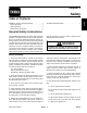
Chapter 1 Safety 1 1 2 3 JACKING INSTRUCTIONS . . . . . . . . . . . . . . . . . . . . . 4 The REELMASTER 5500-D was tested and certified by TORO for compliance with the B71.4-1990 specifications of the American National Standards Institute.
While Operating 9. Sit on the seat when starting and operating the machine. 10.Before starting the engine: A. Engage the parking brake. 16.Operator must be skilled and trained in how to drive on hillsides. Failure to use caution on slopes or hills may cause loss of control and vehicle to tip or roll possibly resulting in personal injury or death. On 4–wheel drive models, always use the seat belt and ROPS together. B. Make sure traction pedal is in NEUTRAL and the ENABLE / DISABLE switch is in DISABLE.
22.Before servicing or making adjustments, stop engine and remove key from the switch. parts of the body away from cutting units and other moving parts. Keep everyone away. 23.Make sure machine is in safe operating condition by keeping all nuts, bolts and screws tight. 30.Do not overspeed the engine by changing governor setting. To assure safety and accuracy, have an Authorized Toro Distributor check maximum engine speed. 24.
Jacking Instructions CAUTION 1 When changing attachments, tires, or performing other service, use correct blocks, hoists, and jacks. Make sure machine is parked on a solid level surface such as a concrete floor. Prior to raising machine, remove any attachments that may interfere with the safe and proper raising of the machine. Always chock or block wheels. Use jack stands or solid wood blocks to support the raised machine.
Chapter 2 Product Records and Maintenance Table of Contents 1 1 2 2 2 3 3 Product Records and Maintenance PRODUCT RECORDS . . . . . . . . . . . . . . . . . . . . . . . . . MAINTENANCE . . . . . . . . . . . . . . . . . . . . . . . . . . . . . . EQUIVALENTS AND CONVERSIONS . . . . . . . . . . . Decimal and Millimeter Equivalents . . . . . . . . . . . . U.S. to Metric Conversions . . . . . . . . . . . . . . . . . . . TORQUE SPECIFICATIONS . . . . . . . . . . . . . . . . . . . Fastener Identification . . . .
Equivalents and Conversions 0.09375 Product Records and Maintenance Page 2 - 2 Rev.
Torque Specifications These Torque Specifications for the installation and tightening of fasteners shall apply to all fasteners which do not have a specific requirement identified in this Service Manual.
Standard Torque for Dry, Zinc Plated, and Steel Fasteners (Inch Series) Thread Size Grade 1, 5, & 8 with Thin Height Nuts SAE Grade 1 Bolts, Screws, Studs, & Sems with Regular Height Nuts (SAE J995 Grade 2 or Stronger Nuts) in–lb in–lb N–cm 10 + 2 13 + 2 147 + 23 # 6 – 32 UNC # 6 – 40 UNF # 8 – 32 UNC 13 + 2 25 + 5 # 10 – 24 UNC 30 + 5 SAE Grade 8 Bolts, Screws, Studs, & Sems with Regular Height Nuts (SAE J995 Grade 5 or Stronger Nuts) in–lb N–cm in–lb N–cm 15 + 2 170 + 20 23 + 2 260 +
Standard Torque for Dry, Zinc Plated, and Steel Fasteners (Metric Fasteners) Class 8.8 Bolts, Screws, and Studs with Regular Height Nuts (Class 8 or Stronger Nuts) Class 10.9 Bolts, Screws, and Studs with Regular Height Nuts (Class 10 or Stronger Nuts) M5 X 0.8 57 + 5 in–lb 640 + 60 N–cm 78 + 7 in–lb 885 + 80 N–cm M6 X 1.0 96 + 9 in–lb 1018 + 100 N–cm 133 + 13 in–lb 1500 + 150 N–cm M8 X 1.25 19 + 2 ft–lb 26 + 3 N–m 27 + 2 ft–lb 36 + 3 N–m M10 X 1.
Other Torque Specifications SAE Grade 8 Steel Set Screws Wheel Bolts and Lug Nuts Recommended Torque Thread Size Recommended Torque** Thread Size Square Head Hex Socket 1/4 – 20 UNC 140 + 20 in–lb 73 + 12 in–lb 5/16 – 18 UNC 215 + 35 in–lb 145 + 20 in–lb 3/8 – 16 UNC 35 + 10 ft–lb 18 + 3 ft–lb 1/2 – 13 UNC 75 + 15 ft–lb 50 + 10 ft–lb 7/16 – 20 UNF Grade 5 65 + 10 ft–lb 88 + 14 N–m 1/2 – 20 UNF Grade 5 80 + 10 ft–lb 108 + 14 N–m M12 X 1.25 Class 8.
Chapter 3 Kubota Diesel Engine INTRODUCTION . . . . . . . . . . . . . . . . . . . . . . . . . . . . . . 2 SPECIFICATIONS . . . . . . . . . . . . . . . . . . . . . . . . . . . . 3 GENERAL INFORMATION . . . . . . . . . . . . . . . . . . . . . 4 Check Engine Oil . . . . . . . . . . . . . . . . . . . . . . . . . . . 4 Fill Fuel Tank . . . . . . . . . . . . . . . . . . . . . . . . . . . . . . . 4 Check Cooling System . . . . . . . . . . . . . . . . . . . . . . . 5 ADJUSTMENTS . . . . . . . . . . . . . . . . . .
Introduction This Chapter gives information about specifications, maintenance, troubleshooting, testing, and repair of the diesel engine used in the Reelmaster 5500-D. test equipment and the specialized nature of some repairs may dictate that the work be done at an engine repair facility. Most repairs and adjustments require tools which are commonly available in many service shops. Special tools are described in the Kubota Workshop Manual, Diesel Engine, 05 Series.
Specifications Item Description Make / Designation Kubota, 4-Cycle, 3 Cylinder, Turbocharged, Water Cooled, Diesel Engine Horse Power 35 HP @ 3000 RPM Bore mm (in.) 78.0 (3.07) Stroke mm (in.) 78.4 (3.09) Total Displacement cc (cu. in.) 1123 (68.53) Torque N-m (ft-lb) 68.2 (50.3) @ 2000 RPM Firing Order 1-2-3 Combustion Chamber Spherical Type No. 2 Diesel Fuel (ASTM D975) Fuel Capacity liters (U.S. gallons) 37.9 (10.
General Information Check Engine Oil 1. Park machine on a level surface, lower cutting units, stop engine, engage parking brake, and remove key from the ignition switch. 2 2. Remove, wipe clean, and reinstall dipstick. Remove dipstick, and check oil level on dipstick. Oil level should be up to FULL mark. 3. If oil is below the FULL mark, remove fill cap and add SAE 10W-30 CD, CE, CF, CF-4, or CG4 oil until level reaches the FULL mark on the dipstick. Do not overfill. Crankcase capacity is 4.0 qt. (3.
Check Cooling System The cooling system is filled with a 50/50 solution of water and permanent ethylene glycol anti-freeze. Check level of coolant at the beginning of each day before starting the engine. System capacity is about 9.6 quarts (9.1 l). 2 1 IMPORTANT: Clean debris off the screen, oil cooler, and front of the radiator daily, and more often if conditions are extremely dusty or dirty (see Engine Cooling System). 1.
Adjustments Adjust Throttle Cable 1. Park machine on a level surface, lower cutting units, stop engine, engage parking brake, and remove key from the ignition switch. 2. Position throttle lever forward so it stops against the seat base slot. 2 1 3. At the fuel injection pump, loosen throttle cable connector on the control lever arm. Note: Do not over tighten the cable connector. The connector must be free to swivel. 4.
Adjust Alternator/Fan Belt The condition and tension of all belts should be checked periodically as recommended in the maintenance schedules in Chapter 2 - Product Records and Manuals. 1 1. Park machine on a level surface, lower cutting units, stop engine, engage parking brake, and remove key from the ignition switch. Open hood. 4 2 Alternator Belt (Fig. 6) 5 2. Check tension by depressing belt midway between alternator and crankshaft pulleys with 22 lb. (9.9 Kg) of force. Belt should deflect 7/16 in.
Service and Repairs Bleed Fuel System 1. Park machine on a level surface, lower cutting units, stop engine, and engage parking brake. 2. Make sure fuel tank is at least half full. Gain access to the engine. 1 2 DANGER Because diesel fuel is highly flammable, use caution when storing or handling it. Do not smoke while filling the fuel tank. Do not fill fuel tank while engine is running, hot, or when machine is in an enclosed area.
Bleed Air from Fuel Injectors IMPORTANT: This procedure should be used only if the fuel system has been purged of air through normal priming procedures (see Bleed Fuel System) and engine will not start. 2 1 1. Park machine on a level surface, lower cutting units, stop engine, and engage parking brake. 3 DANGER 2. Loosen pipe connection to the No. 1 injector nozzle and holder assembly. Figure 11 1. No. 1 injector nozzle 2. No. 2 injector 3. No. 3 injector nozzle 3. Move throttle to FAST position. 4.
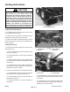
Clean Radiator and Oil Coolers The radiator and oil cooler should be checked for dirt and debris daily, and hourly if conditions are extremely dusty or dirty. 2 1. Park machine on a level surface, lower cutting units, stop engine, engage parking brake, and remove key from the ignition switch. 1 2 CAUTION If engine has been running, the radiator may be hot and cause burns. Work on radiator only when the engine and radiator are cool. Figure 14 1. Screen 2. Latch 2. Open engine hood. 3 3.
Muffler 5 1 7 3 4 15 17 16 8 20 17 9 2 4 11 6 12 15 10 12 21 14 13 20 19 Kubota Diesel Engine 12 15 12 18 Figure 17 1. 2. 3. 4. 5. 6. 7. Muffler Muffler bracket Cap screw Flat washer Muffler clamp Lock nut Exhaust pipe 8. 9. 10. 11. 12. 13. 14. 15. 16. 17. 18. 19. 20. 21.
Fuel System 11 12 29 5 28 33 13 15 2 4 16 3 32 17 35 10 11 14 18 9 19 34 20 8 30 21 7 3 11 6 17 22 31 1 26 35 27 23 30 to 60 in−lb (3.4 to 6.8 N−m) Never Seez 24 25 Figure 18 1. 2. 3. 4. 5. 6. 7. 8. 9. 10. 11. 12. Fuel filter Barbed fitting Fuel fitting Hose clamp Fuel hose Gasket Sending unit Lock washer Round head screw Fuel hose Hose clamp Fuel hose 13. 14. 15. 16. 17. 18. 19. 20. 21. 22. 23. 24.
Fuel Tank Removal Fuel Tank Installation (Fig. 18) 1. Park machine on a level surface, lower cutting units, stop engine, engage parking brake, and remove key from the ignition switch. 1. Install fuel tank to the frame using Figure 18 as a guide. A. Apply antiseize lubricant to the threads of all three cap screws. 2. Drain fuel from the fuel tank into a suitable container by opening the drain fitting. B. Torque all three cap screws from 30 to 60 in-lb (3.4 to 6.8 N-m). 3.
Air Filtering System General Maintenance 2 1 1. Park machine on a level surface, lower cutting units, stop engine, engage parking brake, and remove key from the ignition switch. 2. Check air cleaner, seals, and intake hose for damage which could cause an air leak. Replace damaged air cleaner components as necessary. 3. Service air cleaner filters whenever air cleaner indicator (Fig.
Water/Fuel Separator DANGER Because diesel fuel is highly flammable, use caution when storing or handling it. Do not smoke while filling the fuel tank. Do not fill fuel tank while engine is running, hot, or when machine is in an enclosed area. Always fill fuel tank outside and wipe up any spilled diesel fuel before starting the engine. Store fuel in a clean, safety-approved container and keep cap in place. Use diesel fuel for the engine only; not for any other purpose. 1 2 Figure 21 Draining 1.
Radiator 2 1 3 4 5 7 8 9 21 22 20 15 16 17 18 19 14 23 24 10 25 54 6 11 26 45 44 43 41 53 12 40 42 39 38 52 51 29 13 28 27 30 50 35 34 49 48 47 30 31 46 32 36 37 33 3 Figure 23 1. 2. 3. 4. 5. 6. 7. 8. 9. 10. 11. 12. 13. 14. 15. 16. 17. 18.
Removal 1. Park machine on a level surface, lower cutting units, stop engine, engage parking brake, and remove key from the ignition switch. 8. Remove four cap screws, flat washers and lock washers securing the radiator support to the frame. Pull radiator and support from the frame. 9. Plug any openings to prevent contamination. 2. Open engine hood on the machine. Installation 3. Remove front housing screen from the radiator support. Disconnect hose from the vent tube. 1.
Engine 5 9 8 6 58 4 3 2 1 38 37 65 17 14 52 19 7 3 66 20 18 22 42 10 49 56 49 47 53 37 61 62 36 32 6 44 12 40 67 30 29 50 31 19 27 RH 33 LH 39 19 54 60 24 52 61 58 23 45 68 28 46 23 34 30 57 34 19 34 13 60 51 15 48 53 41 25,26 19 12 53 21 16 34 11 15 16 156 to 204 in−lb (17.6 to 23.1 N−m) Loctite #242 38 36 53 19 37 59 63 43 34 64 19 29 27 19 55 Figure 24 1. 2. 3. 4. 5. 6. 7. 8. 9. 10. 11. 12. 13. 14. 15. 16. 17. 18. 19. 20. 21. 22. 23.
Removal 1. Park machine on a level surface, lower cutting units, stop engine, engage parking brake, and remove key from the ignition switch. 3 2. Open engine hood. 1 3. Disconnect both battery cables at the battery (see Battery Service in Chapter 5 - Electrical system). 2 4. Disconnect yoke flange from the lower fan belt pulley (Fig. 25). Figure 25 1. Lower fan belt pulley 2. Yoke flange Do not open radiator cap or drain coolant if the radiator or engine is hot.
Note: The rear left engine mount does not use a flange nut and flat washer to secure itself to the engine bracket. The cap screw is threaded into the engine bracket. 2 13.Remove flange head nuts, flat washers, cap screws, snubbing washers, and engine mount washers securing the engine mounts to the engine brackets. 1 3 CAUTION One person should operate lift or hoist while the other person guides the engine out of the machine. Figure 28 1. Battery & frame ground 2. ETR solenoid 3.
8. Connect fuel hose to the rear injector nozzle (Fig. 30). 3 6 9. Connect wires and/or electrical connections to the following electrical components: A. Glow plug bus (Fig. 30). High temperature shutdown switch (Fig. 29). B. Battery, frame, and wire harness ground to the engine block and the ETR solenoid (Fig. 28). 5 1 4 2 C. The temperature sender (Fig. 27). The oil low pressure switch, starter, and alternator (Fig 26). 10.Connect air filter hose to the engine. Figure 31 4. Fuel hose (fuel tank) 5.
Fan Drive Hub Disassembly 4 7 1. Secure pulley to prevent it from turning. Remove shaft screw and flat washer. 5 1 2. Press pulley and fan assembly from fan drive hub. 2 3 3. Remove bearings and bearing spacer from fan drive hub. Assembly 6 1. Pressing equally on both inner and outer races, install first bearing into fan drive hub until it contacts shoulder in hub. 2. Place bearing spacer into fan drive hub. 3.
Chapter 4 Hydraulic System Table of Contents For hydraulic steering cylinder and valve information, see Chapter 7 “Steering and Brakes” in this manual. SPECIFICATIONS . . . . . . . . . . . . . . . . . . . . . . . . . . . . 2 GENERAL INFORMATION . . . . . . . . . . . . . . . . . . . . . 3 Hydraulic Hoses . . . . . . . . . . . . . . . . . . . . . . . . . . . . . 3 Hydraulic Fitting Installation . . . . . . . . . . . . . . . . . . . 3 Towing Traction Unit . . . . . . . . . . . . . . . . . . . . . . . . .
Specifications Item Specification Hydraulic Transmission System Relief Pressure (Forward) System Relief Pressure (Reverse) Charge Pressure Cooler By-pass Pressure Filter By-pass Pressure Oil Filter In-line Strainer Sauer-Sundstrand M25, U-type 3625 PSI (249.9 bar) 2755 PSI (190 bar) 150 PSI (10.3 bar) 70 PSI (4.8 bar) 70 PSI (4.8 bar) Screw-on type 260 micron, 8 GPM (30.
General Information Hydraulic Hoses Hydraulic hoses are subject to extreme conditions such as pressure differentials during operation and exposure to weather, sun, chemicals, very warm storage conditions, or mishandling during operation or maintenance. These conditions can cause damage or premature deterioration. Some hoses are more susceptible to these conditions than others. Inspect the hoses frequently for signs of deterioration or damage.
SAE Straight Thread O-Ring Port - Non-adjustable 1. Make sure both threads and sealing surfaces are free of burrs, nicks, scratches, or any foreign material. 2. Always replace the O-ring seal when this type of fitting shows signs of leakage. O-Ring 3. Lubricate the O-ring with a light coating of oil. 4. Install the fitting into the port and tighten it down full length until finger tight. Figure 3 5. Tighten the fitting to the correct flats from finger tight (F.F.F.T.). Size 4 (1/4 in.
Towing Traction Unit IMPORTANT: If towing limits are exceeded, severe damage to the hydrostatic transmission may occur. 1 If it becomes necessary to tow the machine, tow it forward only and at a speed below 3 mph. IMPORTANT: If drive shaft is not removed before towing, the transmission input shaft will not be able to rotate, thus not allowing the transmission to maintain its internal lubrication. Severe damage to the hydrostatic transmission may occur. 1.
Check Transmission Fluid The front axle housing acts as the reservoir for the transmission. The transmission and axle housing hold about 5 quarts (4.7 L) of Mobil 424 hydraulic fluid. Check level of transmission oil daily. 1 1. Position machine on a level surface, lower cutting units, and stop the engine. 2. Remove floor panel. 3. Unscrew dipstick cap from the transmission filler neck; wipe it with a clean rag. Screw dipstick into filler neck. Remove dipstick and check level of oil.
Note: The fluids in this group are interchangeable. Group 1 Hydraulic Fluid (Recommended for ambient temperatures consistently below 100 F.
Hydraulic System (Rev.
Reelmaster 5500-D Page 4 - 9 Hydraulic System (Rev. C) LH RH P1 STEERING CONTROL VALVE V1 P3 100MESH SUCTION STRAINER P2 R3 1450 PSI OUT IN AUX MOW G1 M4 R9 P1 FC1 M5 LC1 FILTER MSV2 R2 Hydraulic System R10 50 PSI P2 2000 PSI MD2 MOW2 M2 R9 C.U. 3 G2 REEL CONTROL MANIFOLD FC2 BKLP2 BACKLAP M3 R9 R9 MOW CIRCUIT R9 LC2 OR2 .025 DIA MOW C.U. 2 COOLER T BACKLAP MSV1 R1 OR1 .025 DIA MD1 BKLP1 3000 PSI M1 R9 R9 R9 R9 C.U. 5 C.U. 1 MOW1 R9 C.U.
Hydraulic System (Rev. C) Page 4 - 10 Reelmaster 5500-D STEERING CONTROL VALVE 1450 PSI 3000 PSI 50 PSI 2000 PSI REEL CONTROL MANIFOLD All solenoids are shown as de-energized.
Reelmaster 5500-D Page 4 - 11 Hydraulic System This page is intentionally blank. Hydraulic System (Rev.
Hydraulic System (Rev.
Traction Circuit An integral charge pump provides a constant supply of charge oil to the variable displacement pump and closed loop circuit for lubrication and to make up for oil that is lost due to internal leakage in the pump and motor. Charge pump flow is directed through the oil cooler, then through the filter to the low pressure side of the closed loop circuit. A cooler bypass valve and filter bypass valve allow charge oil flow to the closed loop if the cooler or filter becomes plugged.
Hydraulic System (Rev. C) Page 4 - 14 Reelmaster 5500-D LH RH P1 V1 P3 100MESH SUCTION STRAINER P2 R3 1450 PSI OUT IN AUX MOW G1 M4 P1 FC1 MOW1 LC1 FILTER T BACKLAP MSV1 R1 OR1 .025 DIA MD1 M5 R9 BKLP1 3000 PSI M1 R9 R9 R9 R9 C.U. 5 C.U. 1 R9 MOW CIRCUIT C.U. 4 R2 R10 50 PSI COOLER MSV2 P2 2000 PSI MD2 MOW2 M2 R9 C.U. 3 FC2 G2 BKLP2 BACKLAP M3 R9 R9 MOW CIRCUIT R9 LC2 OR2 .025 DIA MOW C.U.
Lower Cutting Units A three section, gear pump is driven off the PTO output shaft of the hydrostatic transmission. Pump section (P3) provides oil flow through the steering control valve and lift manifold to all five cutting unit lift cylinders. Maximum circuit pressure (1450 PSI) is limited by a relief valve in the gear pump. When the cutting units are in the raised position, flow from the gear pump (P3) passes through the steering control valve and into the lift manifold.
Hydraulic System (Rev. C) Page 4 - 16 Reelmaster 5500-D LH RH P1 V1 P3 100MESH SUCTION STRAINER P2 R3 1450 PSI OUT IN AUX MOW G1 M4 P1 FC1 MOW1 LC1 FILTER T BACKLAP MSV1 R1 OR1 .025 DIA MD1 M5 R9 BKLP1 3000 PSI M1 R9 R9 R9 R9 C.U. 5 C.U. 1 R9 MOW CIRCUIT C.U. 4 R2 R10 50 PSI COOLER MSV2 P2 2000 PSI MD2 MOW2 M2 R9 C.U. 3 FC2 G2 BKLP2 BACKLAP M3 R9 R9 MOW CIRCUIT R9 LC2 OR2 .025 DIA MOW C.U.
Raise Cutting Units A three section, gear pump is driven off the PTO output shaft of the hydrostatic transmission. Pump section (P3) provides oil flow through the steering control valve and lift manifold to all five cutting unit lift cylinders. Maximum circuit pressure (1450 PSI) is limited by a relief valve in the gear pump. When the cutting units are in the lowered position, flow from the gear pump (P3) passes through the steering control valve and into the lift manifold.
Hydraulic System (Rev. C) Page 4 - 18 Reelmaster 5500-D LH RH P1 V1 P3 100MESH SUCTION STRAINER P2 R3 1450 PSI OUT IN AUX MOW G1 M4 P1 FC1 MOW1 R1 FILTER MSV2 R2 R10 50 PSI P2 2000 PSI MD2 MOW2 M2 R9 C.U. 3 FC2 G2 BKLP2 BACKLAP M3 R9 R9 MOW CIRCUIT R9 LC2 OR2 .025 DIA MOW C.U. 2 COOLER T BACKLAP MSV1 LC1 OR1 .025 DIA MD1 M5 R9 R9 C.U. 5 BKLP1 3000 PSI M1 R9 R9 R9 C.U. 1 R9 MOW CIRCUIT C.U.
Mow and Backlap Mow The reel manifold contains two independent control circuits for the front and rear cutting units. Each circuit is supplied by its own pump section. Pump section (P1) supplies hydraulic power to the front cutting units, while section (P2) supplies the the rear units. Both circuits share manifold port (T), which drains to the oil cooler, oil filter, and on to the hydraulic reservoir.
Hydraulic System (Rev.
Right and Left Turns With the the engine running and the steering wheel in the neutral position (rear wheels positioned straight ahead), the spool of the steering control valve is in the center position. Hydraulic flow enters the steering control valve at the IN port, by-passes the rotary meter (V1) and steering cylinder, and exits through the control valve through the AUX port.
Special Tools Order these tools from your Toro Distributor. Hydraulic Pressure Test Kit - TOR47009 Use to take various pressure readings for diagnostic tests. Quick disconnect fittings provided attach directly to mating fittings on machine test ports without tools. A high pressure hose is provided for remote readings. Contains one each: 1000 PSI (70 Bar), 5000 PSI (350 Bar) and 10000 PSI (700 Bar) gauges. Use gauges as recommended in Testing section of this chapter.
Hydraulic Test Fitting Kit - TOR4079 This kit includes a variety of O-ring Face seal fittings to enable you to connect test gauges into the system. The kit includes: tee’s, unions, reducers, plugs, caps, and male test fittings. Figure 12 Measuring Container - TOR4077 Figure 13 Reelmaster 5500-D Page 4 - 23 Hydraulic System (Rev. C) Hydraulic System Use this container for doing hydraulic motor efficiency testing (motors with case drain lines only).
Troubleshooting The charts that follow contain information to assist in troubleshooting. There may possibly be more than one cause for a machine malfunction. Refer to the Testing section of this Chapter for precautions and specific test procedures. Problem Possible Cause Transmission operates in one direction only. Traction control linkage is faulty. Traction pedal does not return to neutral properly.
Problem Possible Causes Front (Rear) reels will not turn in either direction. Solenoid valve MS1 (MS2) is not shifting. Relief valve R1 (R2) is by-passing. Electrical problem exists (see Chapter 5 - Electrical System). Front (Rear) reels turn too slowly. Relief valve R1 (R2) is by-passing. Mow/Backlap valve MD1 (MD2) is partially rotated. Reel speed valve (FC1) incorrectly adjusted. Reel motor has internal leakage (by-passing oil). Gear pump section P1 (P2) is inefficient.
This page is intentionally blank. Hydraulic System (Rev.
Testing Before Performing Hydraulic Tests IMPORTANT: All obvious areas such as oil supply, filter, binding linkages, loose fasteners, or improper adjustments must be checked before assuming that a hydraulic component is the source of the problem. Precautions for Hydraulic Testing CAUTION Failure to use gauges with recommended pressure (psi) rating as listed in test procedures could result in damage to the gauge and possible personal injury from leaking hot oil.
TEST NO. 1: Traction Circuit Charge Pressure 1. Make sure hydraulic oil is at normal operating temperature by operating the machine for approximately 10 minutes. 1 2. Make sure machine is parked on a level surface with the cutting units lowered and off. Make sure engine is off. CAUTION 2 Prevent personal injury and/or damage to equipment. Read all WARNINGS, CAUTIONS, and Precautions for Hydraulic Testing at the beginning of this section. Figure 14 1. Charge pressure test port 2. Oil filter 3.
TEST NO. 2: Traction Circuit System Relief Pressure 1. Make sure hydraulic oil is at normal operating temperature by operating the machine for approximately 10 minutes. 2. Before doing traction pressure test: Note: The forward and reverse check/high pressure relief valves are different. One valve cartridge has a machined groove on seating surface and must be installed in the ”reverse” port (see Check and High Pressure Relief Valves in Transmission Repairs section). A.
TEST NO. 3: Relief Valve (R1) and (R2) Pressure Note: The front mowing circuit is protected by relief valve (R1). The rear mowing circuit is protected by relief valve (R2). See Hydraulic Flow Diagrams at the beginning of this chapter. 8. Watch pressure gauge carefully while slowly closing the tester flow control valve to fully closed. 1. Make sure hydraulic oil is at normal operating temperature by operating the machine for approximately 10 minutes. From 2950 to 3050 PSI (203.4 to 210.
TEST NO. 4: Gear Pump Section (P1 & P2) Flow (Using Tester with Pressure and Flow Capabilities) Over a period of time, the gears and wear plates in the pump can wear. A worn pump will by-pass oil and make the pump less efficient. Eventually, enough oil can bypass to cause the reels to stall in heavy cutting conditions. Continued operation with a worn, inefficient pump can generate excessive heat and cause damage to seals and other components in the hydraulic system. 1 2 1.
TEST NO. 5: Reel Drive Motor Cross-Over Relief Pressure Use a tee fitting to install pressure gauge in inlet line of motor being tested. NOTE: Inlet is front hose. R9 R9 R9 R9 High Pressure Low Pressure Flow R9 M4 R9 M1 M5 Reel Manifold Block Figure 20 Note: One way to find a bad reel motor is to have another person observe the machine while mowing in dense turf. A bad motor will run slower, produce fewer clippings, and may cause marcelling (or a washboard appearance) on the turf. 1.
Note: The reel motors are connected in series. To isolate a faulty motor, you may have to test all three motors in the circuit by starting with the upstream motor first. 7. One person should sit on the seat and operate the machine while another person reads the tester. Start the engine and move “Enable/Disable” switch to ENABLE. Move “Lower-Mow/Raise” lever forward to engage the cutting units. 3. Lower cutting units, engage parking brake and stop the engine. DESIRED TESTER READING: Approx.
TEST NO. 6: Reel Drive Motor Efficiency (Using Tester with Pressure Gauges and Flow Meter) Outlet hose Case drain hose High Pressure Low Pressure Case Drain Flow R9 R9 R9 Install tester in series between fitting and hose at motor outlet. NOTE: Outlet is rear hose. R9 R9 M4 R9 M1 M5 Disconnect case drain hose (small diameter hose) at bulkhead fitting on frame. Reel Manifold Block Figure 21 Note: Over a period of time, a reel motor can wear internally.
1. Make sure hydraulic oil is at normal operating temperature by operating the machine for approximately 10 minutes. Make sure the hydraulic tank is full. 2. Make sure machine is parked on a level surface with the cutting units lowered and off. Make sure engine is off and the parking brake is engaged. 7. Sit on seat and start the engine. Move throttle to full speed (3200 RPM). Move ”Enable/Disable” switch to ENABLE. Move ”Lower-Mow/Raise” lever forward to engage cutting units. 8.
TEST NO. 7: Gear Pump Section (P3) Flow and Relief Valve Pressure (Using Tester with Pressure Gauges and Flow Meter) 1. Make sure hydraulic oil is at normal operating temperature by operating the machine for approximately 10 minutes. 2 1 2. Make sure machine is parked on a level surface with the cutting units lowered and off. Make sure engine is off. CAUTION Prevent personal injury and/or damage to equipment.
Adjustments Adjust Manifold Relief Valve (R1 and R2) The hydraulic reel circuit is equipped with a relief valve. Valve (R1) is preset at the factory to 3000 PSI (207 bar) and valve (R2) to 2000 PSI (138 bar). However, an adjustment may be required if the setting proves to be off after testing (see TESTING). If an adjustment is required proceed as follows: 2 WARNING Never adjust the relief valve with the hydraulic system pressurized. Hydraulic oil may spray out of the valve with the cap off.
Adjust Traction Drive for Neutral The machine must not creep when traction pedal is released. If it does creep, an adjustment is required. 1. Park machine on a level surface, shut engine off and lower cutting units to the floor. Depress only the right brake pedal and engage the parking brake. 1 2. Jack up left side of machine until front tire is off the shop floor. Support machine with jack stands to prevent it from falling accidentally.
Adjust Cutting Unit Drop Rates The cutting unit lift/lower circuit is equipped with three (3) adjustable flow control valves used to ensure the cutting units do not drop too quickly and damage the turf. Adjust cutting units as follows: 1 2 Center Cutting Unit (Fig. 26) 1. Locate valve behind access panel above operator’s platform. 2. Loosen setscrew on valve and rotate valve approximately 1/2 turn clockwise. 3. Verify drop rate adjustment by raising and lowering cutting unit several times.
Adjust Traction Control Linkage The traction control linkage should not require routine maintenance or adjustment. The following information is provided if the control linkage assembly is disturbed to gain access to other components. Adjust Traction Linkage 2 3 1 1. The machine should be parked on a level surface, cutting units lowered to the floor, and engine off. 2. Connect brake pedals together with locking pin, push both pedals down and pull parking brake latch out. 3.
Service and Repairs General Precautions for Removing and Installing Hydraulic System Components Before Repair or Replacement of Components After Repair or Replacement of Components 1. Before removing any parts from the hydraulic system, park machine on a level surface, engage parking brake, lower cutting units or attachments, and stop engine. Remove key from the ignition switch 1. Check oil level in the hydraulic reservoir and add correct oil if necessary.
Check Hydraulic Lines and Hoses WARNING Keep body and hands away from pin hole leaks or nozzles that eject hydraulic fluid under high pressure. Use paper or cardboard, not hands, to search for leaks. Hydraulic fluid escaping under pressure can have sufficient force to penetrate the skin and cause serious injury. If fluid is injected into the skin, it must be surgically removed within a few hours by a doctor familiar with this type of injury. Gangrene may result from such an injury.
Charge Hydraulic System NOTE: When initially starting the hydraulic system with new or rebuilt components such as motors, pumps, or lift cylinders, it is important that the hydraulic system be charged properly. Air must be purged from the system and its components to reduce the chance of damage. 10.Make sure traction pedal and lift control lever are in neutral. Start engine and run it at low idle of 1150 rpm. The charge pump should pick up oil and fill the hydraulic system.
Change Hydraulic Fluid Change hydraulic fluid after every 800 operating hours, in normal conditions. If fluid becomes contaminated, contact your local TORO distributor because the system must be flushed. Contaminated fluid looks milky or black when compared to clean oil. 1 1. Turn engine off and raise hood. 2. Remove drain plug from bottom of reservoir and let hydraulic fluid flow into drain pan (Fig. 29). Reinstall and tighten plug when hydraulic fluid stops draining.
Replace Hydraulic Oil Filter The hydraulic system filter head is equipped with a service interval indicator. With the engine running, view the indicator, it should be in the GREEN zone. When the indicator is in the RED zone, the filter element should be changed. IMPORTANT: Use only the Toro replacement filter recommended for this product (see parts catalog or service reference decal on unit). Use of any other filter may void the warranty on some components. 1 1.
Replace Transmission Fluid Change the transmission fluid after every 800 hours of operation, in normal conditions. 1 1. Position machine on a level surface, lower the cutting units, stop the engine, engage the parking brakes and remove key from ignition switch. 3 2. Clean area around suction line on bottom of transmission (Fig. 32). Place drain pan under line. 3. Remove line from transmission allowing fluid to drain into drain pan. 2 4. Reinstall suction line to transmission. 5.
Transmission Control Linkage 4 2 27 1 9 5 10 6 11 24 19 11 7 8 3 23 8 21 20 22 26 8 12 13 17 18 17 25 15 8 10 20 16 14 Cotter pin Flat washer Cap screw Screw Neutral switch Switch plate Extension spring Lock nut Cap screw 10. 11. 12. 13. 14. 15. 16. 17. 18. Ball bearing Spacer Cap screw Traction plate Spring anchor plate Lock washer Cap screw Flanged bushing Grease fitting 19. 20. 21. 22. 23. 24. 25. 26. 27.
Transmission 16 1 2 3 18 19 4 5 6 51 20 21 24 22 23 25 26 27 28 29 7 8 9 10 11 12 13 15 14 50 4 54 36 39 38 37 27 49 53 17 25 52 35 34 33 32 31 30 28 41 42 40 43 44 48 47 45 46 Figure 34 1. 2. 3. 4. 5. 6. 7. 8. 9. 10. 11. 12. 13. 14. 15. 16. 17. 18.
Removal 1. Park machine on a level surface, lower cutting units, stop engine, engage parking brake, and remove key from the ignition switch. 2 2. Remove two (2) rear cutting units (see Chapter 8 Cutting Units). 3. To prevent contamination of hydraulic system during removal, thoroughly clean exterior of transmission and differential. 4. Put a drain pan below the transmission. Remove suction line from bottom of in-line filter to let oil drain out of differential (Fig. 35). 1 Figure 35 1. Suction line 5.
8. Install transmission control linkage to the transmission (see Transmission Control Linkage Installation). 9. Secure suction line to top of in-line filter (Fig. 35). 10.Install two (2) rear cutting units (see Chapter 8 - Cutting Units). 11. Install a new filter and fill differential with correct oil. Hydraulic System (Rev. C) 12.Disconnect fuel stop solenoid electrical connector on engine to prevent engine from starting. Prime transmission by turning ignition key switch to crank engine for 10 seconds.
Reelmaster 5500-D Page 4 - 51 Hydraulic System This page is intentionally blank. Hydraulic System (Rev.
Transmission Service 1 7 2 3 4 5 8 9 6 10 11 12 51 50 13 49 14 9 48 6 15 47 46 43 20 19 21 22 16 17 26 45 21 27 36 25 23 19 29 30 31 32 28 44 43 18 22 33 34 21 22 39 20 38 37 19 52 36 35 53 42 41 40 21 20 21 27 26 Figure 38 1. 2. 3. 4. 5. 6. 7. 8. 9. 10. 11. 12. 13. 14. 15. 16. 17. 18.
Disassembly 1. Remove external components as described in the following sections: Shaft Seal Replacement Trunnion Seal Replacement Check/High Pressure Relief Valve Replacement Charge Pressure Relief Valve Replacement Heat Exchanger By-Pass Valve Replacement Filter By-Pass Valve Replacement In-Line Filter Check Valve Replacement Charge Pump Replacement 2. Remove six (6) screws securing the center section to the housing. Note position of longer and shorter screws.
7. Lay transmission on its side and remove motor cylinder block assembly from the housing. Remove pump cylinder block assembly from pump shaft (Fig. 43). Figure 43 IMPORTANT: Pump and motor cylinder block assemblies are identical. To avoid mixing wear patterns, do not mix parts between pump and motor cylinder block assemblies. Make sure each piston is returned to the bore it was taken from. 8. Remove slipper guide and piston assemblies from cylinder blocks (Fig. 44). Figure 44 9.
11. Use an 8-32 machine screw to remove motor shaft bearing retaining pin from housing (Fig. 47). Figure 47 12.Remove motor shaft from housing (Fig. 48). Figure 48 Hydraulic System 13.Press motor shaft out of the bearings and spacer (Fig. 49). Figure 49 14.Remove spiral retaining ring and remove PTO seal guide (with O-ring) from the housing (Fig. 50). Figure 50 Reelmaster 5500-D Page 4 - 55 Hydraulic System (Rev.
15.Slide pump shaft and bearing assembly from housing. Press shaft out of bearing (Fig. 51). Figure 51 16.Remove hex tapping screws retaining the trunnion seal cover and trunnion cover to housing. Mark position of covers for reassembly. The trunnion seal cover assembly includes an O-ring, lip seal, and trunnion bearing on the control side. The trunnion cover assembly includes an O-ring and trunnion bearing on the side opposite the control. Remove these parts from the housing (Fig. 52). Figure 52 17.
Inspection 1. After disassembly, thoroughly clean all parts in a suitable solvent. Replace all O-rings, gaskets and seals. 2. Inspect all parts for damage, nicks, or unusual wear patterns. Replace all parts having unusual or excessive wear or discoloration. 3. If scratches, which can be felt with a pencil lead, can be found on bronze surface of valve plates or running surface of cylinder blocks, polish or replace the parts. 4. Inspect needle bearings in center section.
Note: The trunnion bearings are pressed into the cover assemblies so the split in each bearing will be located closest to the center section. 3. Install trunnion cover (with O-ring and trunnion bearing) into housing and over swashplate trunnion (Fig. 56). 4. Use an arbor press to press a new seal into trunnion seal cover. Outer face of seal should be pressed flush with outer surface of seal cover. Be careful not to damage the seal.
8. Install PTO seal guide and O-ring into housing. Install spiral retaining ring (Fig. 60). Figure 60 9. Press inner bearing, spacer and outer bearing onto motor shaft (Fig. 61). Figure 61 Hydraulic System 10.Install motor shaft assembly into housing (Fig. 62). Figure 62 11. Install motor shaft bearing retaining pin into housing (Fig. 63). Figure 63 Reelmaster 5500-D Page 4 - 59 Hydraulic System (Rev.
12.Install pipe plug over motor shaft bearing retaining pin and tighten to a torque of 6 to 9 ft.-lb (8 to 12 N-m) (Fig. 64). Figure 64 13.Coat thrust plates with petroleum jelly and install into housing and swashplate (Fig. 65). The thrust plates are reversible. Figure 65 14.Assemble each cylinder block kit by installing piston assemblies into the slipper guide. Lubricate pistons and cylinder block bores.
17.Install valve plate locating pins into center section (Fig. 68). Figure 68 18.Coat back (steel side) of valve plates with petroleum jelly to hold them in position and install valve plates onto center section, with their bronze faces visible (Fig. 69). The notch on each valve plate must engage its locating pin. Note: Do not interchange pump and motor valve plates when assembling transmission. The motor valve plate has grooves on both sides of the plate.
IMPORTANT: Make sure all parts are properly aligned. Do not force center section into position on the housing. 20.Install center section with valve plates onto transmission housing (Fig. 72). Note: When the center section is properly installed, the cylinder block springs will hold the end center section away from the housing about 1/8 inch (3.1 mm). Figure 72 21.Install six (6) screws that retain the center section to the housing and torque evenly to 33 to 41 ft.-lb (45 to 56 N-m) (Fig. 73). 22.
Shaft Seal Replacement 1. Park machine on a level surface, lower cutting units, stop engine, engage parking brake, and remove key from the ignition switch. 1 2. Disconnect drive shaft from the transmission (Fig. 74). Note: The face of the seal my be punctured with a sharp instrument (such as a screwdriver) to aid in prying the seal out, or a slide hammer type puller may be used to remove the seal. Be careful to not damage the charge pump cover or shaft. Once removed the seal is not reusable. Figure 74 1.
Trunnion Seal Replacement 4 1. Park machine on a level surface, lower cutting units, stop engine, engage parking brake, and remove key from the ignition switch. 3 1 2. Remove pump control from the swashplate control shaft on transmission (see Hydraulic Transmission Control Linkage Removal). 2 3. Remove hex tapping screws retaining trunnion seal cover to transmission housing (Fig. 76). 4. Remove trunnion seal cover with lip seal and O-ring. 5. Put seal cover in an arbor press and press out old seal.
High Pressure Relief/Check Valve Replacement 1. Park machine on a level surface, lower cutting units, stop engine, engage parking brake, and remove key from the ignition switch. 5 4 2. Remove check/high pressure relief valve hex plug (Fig. 77). 1 3 3. Remove the valve cartridge assembly. Inspect the valve and mating seat in the housing for damage or foreign material. It will be necessary to replace the center section if the seat is damaged.
Charge Pressure Relief Valve Replacement 1. Park machine on a level surface, lower cutting units, stop engine, engage parking brake, and remove key from the ignition switch. 2. Remove the charge relief valve plug (Fig. 78). 3. Remove the spring and poppet from the housing. 4. Do not interchange parts with another valve. 5. Inspect the poppet and mating seat in the end cap for damage or foreign material.
Heat Exchanger By-Pass Valve Replacement 1 1. Park machine on a level surface, lower cutting units, stop engine, engage parking brake, and remove key from the ignition switch. 2 3 4 2. Remove the heat exchanger bypass valve hex plug (Fig. 79). 3. Remove the spring and poppet from the housing. 4. Do not interchange parts with another valve. The spring used in the heat exchanger bypass valve is identified by a yellow dye mark, and requires a force of approximately 5.5 lb (24.
Filter By-Pass Valve Replacement 1. Park machine on a level surface, lower cutting units, stop engine, engage parking brake, and remove key from the ignition switch. 2. Remove the filter by−pass valve hex plug (Fig. 80). 3. Remove the spring and poppet from the housing. 4. Do not interchange parts with another valve. The spring used in the filter by−pass valve is identified by a red dye mark, and requires a force of approximately 2.2 lb (9.8 N) to compress it to a length of 1.280 inch (3.25 cm).
Charge Pump Replacement 1. Park machine on a level surface, lower cutting units, stop engine, engage parking brake, and remove key from the ignition switch. 1 2. Remove the transmission to engine driveshaft (Fig. 82). 3. Remove the two (2) cap screws retaining the charge pump cover. Remove the charge pump (Fig. 83). 2 4. Remove geroter drive pin from the groove in the shaft. 5. Remove the geroter assembly from the charge pump cover. Remove the shaft seal from the cover. Figure 82 1. Drive shaft 2.
Gear Pump 9 21 8 5 4 6 1 2 7 3 20 10 19 11 12 13 18 17 16 15 14 Figure 84 1. 2. 3. 4. 5. 6. 7. Suction hose Hose clamp Hydraulic fitting Cap screw Lock washer Gasket Transmission coupler 8. 9. 10. 11. 12. 13. 14. Transmission adapter O-ring Hydraulic straight fitting O-ring Hydraulic hose Hydraulic hose Hydraulic hose 15. 16. 17. 18. 19. 20. 21. O-ring Hydraulic straight fitting O-ring Gear pump O-ring O-ring Flat washer Removal Installation 1.
Reelmaster 5500-D Page 4 - 71 Hydraulic System This page is intentionally blank. Hydraulic System (Rev.
Gear Pump Service 2 1 3 4 5 Install with sharp edge facing out 6 7 8 Install with sping side facing in 9 10 15 11 16 12 9 13 5 4 17 14 9 18 15 16 15 5 21 15 20 16 16 15 9 4 22 23 24 50 to 55 ft−lb (68 to 75 N−m) 25 Figure 85 1. 2. 3. 4. 5. 6. 7. 8. 9. Retaining ring Shaft seal Flange Anti extrusion seal (SKP2) Pressure loading seal (SKP2) O-ring − 2.612” (66 mm) dia. Dowel pin Housing O-ring − 2.675” (68 mm) dia. Hydraulic System (Rev. C) 10. 11. 12. 13. 14. 15. 16. 17.
sections. Be careful not to drop parts or disengage gear mesh. 1. Remove pump (see Pump Removal and Installation). 2. Plug ports and wash exterior of pump with cleaning solvent. Make sure parts and work area are clean. 3. Remove shaft seal retaining ring. 4. Remove and dispose of the seal. Note: Seal can be removed by punching two holes in face of seal 180 apart, installing metal screws and pulling seal out by grasping the screws. IMPORTANT: Do not try to pry the seal out of the pump.
Reel Motor Service 1 2 3 4 5 6 Use seal protector tool TOR4072 when inserting shaft through seal. 7 8 NOTE: Seal protector tool is part of TOR4070 Cutting Unit Tool Kit shown in Chapter 8 Cutting Units. 40 to 45 ft−lb (54 to 61 N−m) Figure 87 1. Retaining Ring 2. Shaft seal 3. Flange 4. E-Seal 5. O-Ring 6. Dowel pin 7. Valve Block 8. Adjusting valve Removal 1. Park machine on a level surface, lower cutting units, stop engine, engage parking brake, and remove key from the ignition switch. 1 2.
Adjusting Valve (Cross-over Relief Valve) Service Note: The adjusting valve (#8 Fig. 87) must be replaced as a complete assembly. Disassemble parts for cleaning and inspection only. 9. Before removing gear set, apply marking dye to mating teeth to retain “timing”. Motor efficiency may be affected if the teeth are not installed in the same position during reassembly. 10.Remove idler gear. 1. Disassemble the adjusting valve parts. DO NOT attempt to remove the valve seat.
Reassembly 1. Put flange on a flat surface with shaft seal facing down. Make sure back side of flange is free of contamination (Fig. 87). 2. Put front bearing block, seal side down, on flange. 3. Apply a light coating of oil to exposed face of bearing block. Put tape or seal protector tool (TOR4072) over splined end of drive shaft. Insert drive shaft through bearing block and shaft seal. 4. Put idler gear on bearing block. Apply a light coating of oil to back face of drive and idler gears. 5.
Reelmaster 5500-D Page 4 - 77 Hydraulic System This page is intentionally blank. Hydraulic System (Rev.
Hydraulic Control Manifolds 22 23 32 8 12 11 21 13 19 20 24 2 4 28 1 25 3 19 28 18 7 19 20 17 11 21 13 29 5 9 10 6 12 14 5 30 15 16 26 31 27 Figure 89 (Reel Manifold) 1. 2. 3. 4. 5. 6. 7. 8. 9. 10. 11. Straight hydraulic fitting O-ring O-ring Hydraulic tube Straight hydraulic fitting O-ring O-ring Control manifold Flat washer Safety switch Test port fitting 12. 13. 14. 15. 16. 17. 18. 19. 20. 21. 22.
17 15 28 41 32 16 4 23 19 9 23 18 19 18 19 14 34 5 18 20 20 10 20 11 12 33 10 16 15 17 26 22 37 20 35 36 9 8 16 7 3 18 7 6 13 15 17 17 31 38 2 27 21 24 19 25 30 40 4 15 16 39 31 29 29 30 31 1 26 1. 2. 3. 4. 5. 6. 7. 8. 9. 10. 11. 12. 13. 14. Hydraulic hose Hydraulic hose Hydraulic hose Clamp Lift manifold Hydraulic tee fitting O-ring O-ring 90o hydraulic barb fitting O-ring Test port cap Test port fitting O-ring Hydraulic tube 15. 16. 17. 18. 19. 20. 21.
Hydraulic Control Manifold Service 20 21 24 Reel Speed 45 ft−lb (61 N−m) 4 Backlap 55 to 60 ft−lb (75 to 81 N−m) 23 6 26 25 27 28 22 5 2 to 5 ft−lb (2.7 to 6.8 N−m) 12 30 3 33 32 29 38 7 35 34 36 31 37 11 10 Loctite 242 R2 R1 7 FC2 9 MD2 MS2 8 45 ft−lb (61 N−m) MS1 MD1 FC1 Backlap 55 to 60 ft−lb (75 to 81 N−m) P2 10 P1 3 14 15 G1 13 LC1 Reel Speed 45 ft−lb (61 N−m) 2 1 19 17 18 16 Figure 91 (Reel Manifold) 1. 2. 3. 4. 5. 6. 7. 8. 9. 10. 11. 12. 13.
2 to 5 ft−lb (2.7 to 6.8 N−m) 8 15 15 7 5 Loctite 242 6 4 45 ft−lb (61 N−m) 1 3 5 2 SV5 SV3 14 SV1 SV2 10 9 P1 12 Hydraulic System SV4 13 11 Figure 92 (Lift Manifold) 1. 2. 3. 4. 5. Plug Cartridge valve (4 way) Seal kit Cartridge valve (N.O.) Seal kit 6. 7. 8. 9. 10. Cartridge valve (N.C.) Solenoid (28 watt) Solenoid seal Plug O-ring 11. 12. 13. 14. 15. Plug O-ring Plug O-ring Solenoid (20 watt) Note: The ports on the manifold(s) are marked for easy identification of components.
7. Reinstall the cartridge valve: Solenoid Operated Cartridge Valves A. Lubricate new O-rings and backup rings of seal kit with clean hydraulic oil and install. The O-ring and backup ring must be arranged properly on the cartridge valve for proper operation and sealing. 1. Make sure the manifold is clean before removing the valve. 2. Remove nut securing solenoid to the cartridge valve. Slide solenoid and both O-rings off the valve. Note: Use care when handling the cartridge valve.
6. Reinstall the cartridge valve: 6. Reinstall relief valve cartridge: A. Lubricate new O-ring and backup ring of seal kit with clean hydraulic oil and install. The O-ring and backup ring must be arranged properly on the cartridge valve for proper operation and sealing. Note: There are two different types of manual rotary cartridge valves: flow control (reel speed − size 10) and 4−way directional control (backlap − size 12). Installation torque vales are different for each type. B.
J. On flow control valve cartridge, turn knob counterclockwise until the arrow points at the number ”5”. Simultaneously tighten upper jam nut and turn knob so it is tight and the arrow is pointing at the number ”1” on the locating plate. CAUTION Use eye protection such as goggles when using compressed air. Logic Cartridge 1. Make sure the manifold is clean before removing logic cartridge valve and seal kit. Remove cartridge valve. 2.
Flow Divider The lift circuit for the front, outer lift cylinders includes a flow divider. This flow divider provides for even lifting of cutting units #4 and #5. The lift speed of #4 and #5 cutting units should be similar when the flow divider is functioning correctly. The flow divider assembly mounts to the front carrier frame (Fig. 93). 5 4 6 7 2 8 3 4 2 1 The flow divider on early production machines consists of a three (3) port manifold and a flow divider cartridge.
Lift Cylinders Removal 1. Read the General Precautions for Removing and Installing Hydraulic System Components at the beginning of the Service and Repairs section of this chapter. 2. Disconnect hydraulic hoses from lift cylinder. 3 4 3. Remove front right or front left lift cylinder. 2 A. Remove retaining ring from the cylinder rod end pin. Remove cylinder pin with remaining retaining ring and thrust washers from the lift arm and cylinder clevis (Fig. 95). B.
2. Install front center lift cylinder (Fig. 97). A. Insert cylinder pin through the carrier frame and cylinder clevis. Secure self tapping screw to the cylinder pin and carrier frame. 3 1 2 B. Insert cylinder pin with attached retaining ring and thrust washer through the lift arm and cylinder clevis. Secure thrust washer and retaining ring to the cylinder rod end pin. 4 5 6 7 3. Install front right or left lift cylinder. A. Insert cylinder pin through carrier frame and cylinder clevis.
Lift Cylinder Service SERIAL NUMBER BELOW 250000000 1 2 13 4 5 3 7 8 6 9 10 11 12 FRONT LEFT AND FRONT RIGHT LIFT CYLINDER SHOWN Figure 99 1. 2. 3. 4. 5. 6. 7. 8. 9. Barrel with clevis Nut Uni-ring Piston 10. 11. 12. 13. O-ring Rod seal O-ring Back-up ring Head Dust seal Collar Shaft with clevis Grease fitting SERIAL NUMBER ABOVE 260000000 9 30 to 35 ft−lb (41 to 47 N−m) 10 11 12 8 13 4 14 5 2 7 3 6 1 FRONT LEFT AND FRONT RIGHT LIFT CYLINDER SHOWN Figure 100 1. 2. 3. 4. 5.
Disassembly Reassembly 1. Remove oil from lift cylinder into a drain pan by slowly pumping the cylinder shaft. Plug both ports and clean the outside of the cylinder. 1. Make sure all cylinder parts are clean before reassembly. IMPORTANT: Prevent damage when clamping the cylinder’s barrel into a vise; clamp on the clevis only. Do not close vise enough to distort the barrel. 2. Coat new O-rings, Uni-rings, rod seal, back-up ring, and dust seal with clean hydraulic oil.
Hydraulic Reservoir 2 17 6 16 22 18 4 20 3 1 21 12 19 11 13 19 24 15 23 14 32 Thread Sealant 29 35 34 5 25 28 33 30 to 60 in−lb (3.4 to 6.8 N−m) Never Seez 31 12 36 10 8 30 9 11 7 26 19 27 21 Figure 101 1. 2. 3. 4. 5. 6. 7. 8. 9. 10. 11. 12. Hydraulic reservoir Tank breather Filler screen Dipstick Filter bracket Plastic plug Hydraulic straight fitting O-ring O-ring Screw cap 90o hydraulic fitting O-ring Hydraulic System (Rev. C) 13. 14. 15. 16. 17. 18. 19. 20. 21. 22. 23. 24.
Removal Hydraulic Reservoir Installation 1. Park machine on a level surface, lower cutting units, stop engine, engage parking brake, and remove key from the ignition switch. 1. Install reservoir (Fig. 101). Note: The electrical harness dose not have to be disconnected to remove the right fender and control console from the frame. 2. Remove right fender with control console attached enough to allow removal of the hydraulic reservoir. 3.
Hydraulic Oil Cooler and Transmission Heat Exchanger Removal CAUTION 1 The radiator and oil cooler may be hot. To avoid possible burns, allow the engine and cooling systems to cool before working on the oil cooler. 3 1. Carefully lift the hydraulic oil cooler or the transmission heat exchanger up and out of its support hooks (Fig. 102). 2. Disconnect the hydraulic hoses at each end of the cooler/heat exchanger and remove it from the vehicle. 2 Figure 102 1. 2. Oil cooler Heat exchanger 3.
Chapter 5 Electrical System Table of Contents Reelmaster 5500-D Run (ETR) Solenoid (Solenoid With 3 Wire Connector) . . . . . . . . . . . . . . . . . . . . . . . . . . . . . . Run (ETR) Solenoid (Solenoid With 2 Wire Connector) . . . . . . . . . . . . . . . . . . . . . . . . . . . . . . Fuel Sender . . . . . . . . . . . . . . . . . . . . . . . . . . . . . . . Fuel Gauge . . . . . . . . . . . . . . . . . . . . . . . . . . . . . . . Temperature Sender . . . . . . . . . . . . . . . . . . . . . . . .
Electrical Schematic, and Electrical Harness and Connectors Drawings The electrical schematic and other electrical drawings for the Reelmaster 5500-D are located in Chapter 10 Electrical Diagrams. Electrical System (Rev.
Special Tools Order special tools from your Toro Distributor. Some tools may also be available from a local supplier. Multimeter The meter can test electrical components and circuits for current, resistance, or voltage. NOTE: Toro recommends the use of a DIGITAL VoltOhm-Amp multimeter when testing electrical circuits. The high impedance (internal resistance) of a digital meter in the voltage mode will make sure that excess current is not allowed through the meter.
Toro Automated Control Electronics Diagnostic Tool Diagnostic ACE Display The diagnostic display is connected to the wiring harness connector located inside the control console to help the user verfiy correct electrical functions of the machine (Fig. 3 and 4). Overlay Diagnostic ACE Display ACE Display (Toro Part No. 85-4750) Overlay for RM 5500-D (Toro Part No.
Troubleshooting CAUTION Remove all jewelry, especially rings and watches, before doing any electrical troubleshooting or testing. Disconnect the battery cables unless the test requires battery voltage. For effective troubleshooting and repairs, you must have a good understanding of the electrical circuits and components used on this machine (see Electrical Schematics and Electrical Harness and Connectors Drawing section of this chapter).
Check Interlock Switches The purpose of the interlock switches is to prevent the engine from cranking or starting unless the traction pedal is in NEUTRAL, the Enable / Disable switch is in DISABLE and the Lower Mow / Raise control is in the neutral position. The engine will stop when the traction pedal is depressed with operator off the seat. In addition, the engine will stop if the traction pedal is depressed and the parking brake is engaged.
If no output LED’s are blinking, but the correct output LED’s do not illuminate, verify that the required input switches are in the necessary positions to allow that function to occur. Verify correct switch function. If the output LED’s are on as specified, but the machine does not function properly, this indicates a non-electrical problem. Repair as necessary.
Starting Problems Problem Possible Causes All electrical power is dead, including gauges. The battery charge is low. The ignition switch or circuit wiring is faulty. The fusible link from the battery is faulty. The 20 ampere fuse to the ignition switch is open. Starter solenoid clicks, but starter will not crank. Low battery charge. Note: If the solenoid clicks, the problem is not in the in- Loose or corroded battery cables. terlock circuit wiring or the ECU. Loose or corroded ground.
General Run and Transport Problems Engine continues to run, but should not, when the ignition switch is turned off. The engine run (ETR) solenoid is stuck open. Engine continues to run, but should not, when the traction pedal is engaged with no operator in the seat. The seat sensor or circuit wiring is faulty. The engine stops during operation, but is able to restart. The parking brake is engaged. Ignition switch or circuit wiring is faulty. Traction neutral switch or circuit wiring is faulty.
Cutting Unit Operating Problems (Cont.) Cutting units run, but should not, when lowered with enable/disable switch in the disable position. The enable/disable switch or circuit wiring is faulty. The front cutting units do not operate in either direction. Units are able to raise and lower. Rear cutting units operate. Solenoid MSV1 or circuit wiring is faulty. A hydraulic problem exists (see Troubleshooting section of Chapter 4 - Hydraulic System).
TurfDefender Leak Detector Note: The 4 beep signal may occur if machine is started on a slope. Move machine to a level surface, move ignition key to “OFF” position, wait 5 seconds, then move key to “ON” position to restart the system. If the alarm gives a loud continuous beep while mowing and shuts off the cutting units, it means that a leak has been detected. On the traction unit, the red light on the steering console will also blink indicating the ECU has shut off the cutting units. 1.
If 4 beeps are heard: If false alarms are observed: The most common cause for a 4 beep signal is from an improper oil level reading. Make sure machine is on a level surface when checking oil level. Since oil level will vary with temperature, it is best to check when cool. 1. Oil level may be low causing air to be drawn into the system. Check oil level. 1. When toggling “input”, a LED should display (Fig.
1 Diagnostic ACE Display Functions 1. 2. 3. 4. 2 3 Overlay decal (English shown) “Inputs Displayed” LED (Red) “Outputs Displayed” LED (Green) Toggle button 4 Figure 8 Using “Inputs Displayed” (Red Text) 1 2 1. 2. 3. 4. 5. LED lit if oil level is too high LED lit if oil level is OK LED lit if oil level is too low LED lit if oil is too hot LED lit if system air leak has been detected 6. One or two LED’s lit displaying relative position of the Turfdefender’s internal float. 7.
Electrical System (Rev. C) ELECTRIC SOLENOID VALVE BLK RED BLK/Y RED/Y − Page 5 - 14 LEAK DETECTOR ALARM C C B E E B A A TURF DEFENDER LOOPBACK I.D.
Electrical System Quick Check Battery Test (Open Circuit Test) Use a multimeter to measure the voltage between the battery terminals. Voltage Measured Battery Charge Level 12.68 V (or higher) Fully charged (100%) Set multimeter to the DC volts setting. The battery should be at a temperature of 60 to 100 F (16 to 38 C). The ignition key should be off and all accessories turned off.
Component Testing For accurate resistance and/or continuity checks, electrically disconnect the component being tested from the circuit (e.g. unplug the ignition switch connector before doing a continuity check). NOTE: For more component testing information, see the Kubota Workshop Manual, Diesel Engine, 05 Series at the end of Chapter 3 - Kubota Diesel Engines.
Glow and Start Relays The start relay is attached to the radiator shield, and the glow relay mounts to the hydraulic oil filter bracket. Both relays are located below the seat (Fig. 12). 3 Note: The start relay may be manufactured by one of three different manufacturers. Verify manufacturer name and part number before performing the resistance check on the relay coil. Note: Prior to taking small resistance readings with a digital multi meter, short the test leads together.
Fuses The fuse blocks are located under the control panel and inside the control console. Identification, Function, and Wiring The fuses are held in two fuse blocks. Use Figure 16 to identify each individual fuse and its correct amperage. Each fuse holder has the following functions and wire connected to it. 2 1 Fuse A1 A. Supplies power to Electronic Control Unit (ECU) terminals 1L and 1M. B. Has blue/white wire (1L), green/black wire (1M) and red wire (battery). Figure 15 1. Fuse block A Fuse A2 2.
Hydraulic Valve Solenoids Note: Prior to taking small resistance readings with a digital multimeter, short the test leads together. The meter will display a small resistance value (usually 0.5 ohms or less). This resistance is due to the internal resistance of the meter and test leads. Subtract this value from the measured value of the component you are testing. 1 2 8 3 4 7 1. Make sure engine is off. Disconnect solenoid valve electrical connector. 5 6 2. Apply 12VDC source directly to the solenoid.
High Temperature Warning and Shutdown Switch The high temperature warning and shut down switch is located on the right side of the water flange that is attached to the front of the engine cylinder head. There is a green/white wire attached to the switch (Fig. 19). 2 1 CAUTION Make sure engine is cool before removing the temperature switch. 1. Lower coolant level in the engine and remove the temperature switch. Figure 19 2. Put switch in a container of oil with a thermometer and slowly heat the oil (Fig.
Warning Light Cluster Note: Individual light bulbs can be tested by removing them from the lighting cluster and applying 14 VDC to their wiring terminals. 1 2 3 4 Testing Cluster Removed from Connector. 1. Apply 14 VDC to pin D. 5 2. Ground pins F, A, and E. 3. Lamps 1, 2, and 3 should light. 4. Apply 14 VDC to pin B. 2 1 5. Ground pin C. 6. Lamp 4 should light. 6 Oil Pressure Light The oil pressure light should come on when the ignition switch is in the ON position with the engine not running.
Run (ETR) Solenoid (Solenoid With 3 Wire Connector) The run (ETR) solenoid must be energized for the engine to run. It is mounted on the engine block near the injection pump. 2 In Place Testing Note: Prior to taking small resistance readings with a digital multimeter, short the test leads together. The meter will display a small resistance value (usually 0.5 ohms or less). This resistance is due to the internal resistance of the meter and test leads.
Run (ETR) Solenoid (Solenoid With 2 Wire Connector) The run (ETR) solenoid must be energized for the engine to run. It is mounted on the engine block near the injection pump. 2 1 In Place Testing Note: Prior to taking small resistance readings with a digital multimeter, short the test leads together. The meter will display a small resistance value (usually 0.5 ohms or less). This resistance is due to the internal resistance of the meter and test leads.
Fuel Sender The sender is located on top of the fuel tank under the right, front fender. 1. Remove blue/green wire and black ground wire from the sender. 2 2. Remove round head screws and lock washers from the sender and fuel tank. 3. Remove sender and gasket from the fuel tank. Clean any fuel from the sender. Note: Before taking small resistance readings with a digital multimeter, short test leads together. The meter will display a small resistance value.
Fuel Gauge The fuel gauge can be tested using a new gauge as a substitute or by the use of a DC voltage source and a variable resistance box. CAUTION Make sure the voltage source is turned OFF before connecting it to the electrical circuit to avoid electrical shock and prevent damaging the gauge. VARIABLE RESISTANCE 14 VDC + 0.01 VDC 1. Connect fuel gauge to the variable resistance and DC voltage source (Fig. 29).
Temperature Sender The sender is located on the left side of the water flange that is attached to the front of the engine cylinder head. There is a blue/white wire attached to the terminal of the switch (Fig. 31). 1 1. Lower coolant level in the engine and remove the high temperature sender. 2. Put switch in a container of oil with a thermometer and slowly heat the oil (Fig. 32). 2 CAUTION Figure 31 Handle the hot oil with extreme care to prevent personal injury or fire. 1. Temperature sender 2.
Temperature Gauge The temperature gauge can be tested using a new gauge as a substitute or by the use of a DC voltage source and a variable resistance box. CAUTION Make sure the voltage source is turned OFF before connecting it to the electrical circuit to avoid electrical shock and prevent damaging the gauge. VARIABLE RESISTANCE 14 VDC + 0.01 VDC 1. Connect temperature gauge to the variable resistance and DC voltage source (Fig. 29).
Hour Meter The meter is either located on the control panel or under the control panel inside the control console. Hobbs 1. Connect the positive (+) terminal of a 12 VDC source to the positive terminal of the hour meter. QUARTZ 00001 HOURS 2. Connect the negative (-) terminal of the voltage source to the other terminal of the hour meter. 1 10 + 3. The hour meter should move a 1/10 of an hour in six minutes. 4. Disconnect voltage source from the hour meter.
Traction Speed Sensor The sensor is located on the right side of differential gear box that is part the front axle. It uses a magnetically biased Hall Effect integrated circuit. As the spur gear turns in the differential, the sensor accurately senses the movement of the gear teeth passing by the sensor. The red connector wire is the positive lead, the black wire is the ground lead, and the gray wire is the signal output. 2 1 The sensor is tested as part of the output checks with the Diagnostic ACE tool.
Speedometer The speedometer can be tested using a DC pulse generator, or by verifying the gear tooth sensor is operating properly and operating the machine with the wheels off the ground. 2 1 CAUTION 3 Pulse Generator 14 VDC + 0.01 VDC Make sure the voltage source is turned OFF before connecting it to the electrical circuit to avoid electrical shock and prevent damaging the gauge. 14 VDC + 0.01 VDC Using Pulse Generator − 1. Connect speedometer to the pulse generator and DC voltage source (Fig. 38).
3. Start engine. Verify pinion shaft or traction shaft (4WD units) speed (RPM) with phototac. Check corresponding speed on the speedometer (Fig. 40 and 41). 2 4. Turn off engine. Replace meter as necessary. 1 Pinion Speed (RPM) Speedometer (MPH) 291.2 4 582.4 8 873.6 12 Figure 41 1. Traction shaft (4WD) 2. Differential housing Reels Enable/Disable and Backlap Switches The reels enable/disable switch is attached to the instrument panel.
Traction Neutral Switch The switch is located on the right side of the transmission. It uses its normally open contact that is closed by the switch arm depressing the plunger when the traction pedal is in the neutral position. When the traction pedal is depressed in either the forward or reverse direction, the switch arm releases the plunger on the switch and its normally open contact opens. 1 2 3 2 4 Figure 45 1. Plunger 2. Ground 3. Normally open 4. Normal closed 1 Figure 44 1. Transmission 2.
Joystick Raise and Lower/Mow Switches Two micro switches for the joy stick are located in the lift control mechanism that is inside the control console. The rear switch on the mechanism is used to lower the reels and the front switch to raise them. A normally open contact closes when the joy stick is positioned to either to lower or raise the reels. Each switch has an electrical connector to make sure the normally closed contact on the switch is not used.
Front Reels Down Sensor (Serial Number Below 230000000) On machines with serial numbers below 230000000, the front reels down sensor consists of two parts. The reed switch is located on the left end of the carrier frame and has a normally open contact. The switch actuator is located on the left lift arm and is made of a magnetic material. When the front reels are lowered, the magnetic field of the actuator is positioned near the reed switch, and the contact in the switch closes.
Service and Repairs NOTE: For more component repair information, see the Kubota Workshop Manual, Diesel Engine, 05 Series at the end of Chapter 3 - Kubota Diesel Engines. Battery Storage 3. Leave cables disconnected if the battery is stored on the machine. If the machine will be stored for more than 30 days 1. Remove the battery and charge it fully (see Battery Service). 4. Store battery in a cool atmosphere to avoid quick deterioration of the battery charge. 2.
Battery Service The battery is the heart of the electrical system. With regular and proper service, battery life can be extend. Additionally, battery and electrical component failure can be prevented. 3 1 2 CAUTION When working with batteries, use extreme caution to avoid slashing or spilling electrolyte. Electrolyte can destroy clothing and burn skin or eyes. Always wear safety goggles and a face shield when working with batteries. Figure 50 1. Ground cable 2.
2. Conduct a hydrometer test of the battery electrolyte. D. Measure the temperature of the center cell. IMPORTANT: Make sure the area around the cells is clean before opening the battery caps. E. Connect a battery load tester to the battery terminals following the manufacturer’s instructions. Connect a digital multimeter to the battery terminals. A. Measure the specific gravity of each cell with a hydrometer.
7. Connect a digital multimeter (set to amps) between the negative battery post and the negative (ground) cable connector. The reading should be less than 0.1 amp. If the reading is 0.1 amp or more, the unit’s electrical system should be tested and repaired. 8. Connect negative (ground) cable connector to the negative battery post. Tighten cap screw and lock nut with two wrenches. Battery Reserve Capacity (Minutes) 75% 50% 25% 0% 80 or less 3.8 hrs @ 3 amps 7.5 hrs @ 3 amps 11.
Traction Speed Sensor Replacement Removal 2 1. Park machine on a level surface, lower cutting units, stop engine, engage parking brake, and remove key from the ignition switch. 1 2. Jack up the front end of the machine about 1 ft. (30 cm) to prevent transmission fluid from leaking from the gear box when the sensor is removed (see Jacking Instructions in Chapter 1 - Safety). 4 5 3 3. Disconnect electrical connector from the harness.
Electrical System (Rev.
Chapter 6 Differential Axle Table of Contents INTRODUCTION . . . . . . . . . . . . . . . . . . . . . . . . . . . . . . SPECIFICATIONS . . . . . . . . . . . . . . . . . . . . . . . . . . . . SPECIAL TOOLS . . . . . . . . . . . . . . . . . . . . . . . . . . . . . SERVICE and REPAIRS . . . . . . . . . . . . . . . . . . . . . . . Axle Assembly Removal and Installation . . . . . . . . Axle Shafts and Wheel Bearings . . . . . . . . . . . . . . . Lubrication . . . . . . . . . . . . . . . . . . . . . . . . . . . .
Specifications Item Specification Front wheel lug nut torque 45 to 55 ft-lbs (61 to 75 Nm) Front to rear housing torque 18 to 28 ft-lbs. (24 to 38 Nm) Transmission to axle torque 25 to 30 ft-lbs. (34 to 41 Nm) Differential bearing cap torque 30 to 45 ft-lbs. (41 to 61 Nm) Ring gear to differential case torque 45 to 65 ft-lbs. (61 to 89 Nm) Fill pipe torque 20 to 30 ft-lbs. (27 to 41 Nm) Side plate (gear cover) torque 25 to 40 ft-lbs.
Service and Repairs Axle Assembly Removal and Installation 1. Put machine on a level surface, lower cutting units, stop the engine and remove key from ignition switch. Block rear wheels to prevent machine from moving. 2. Remove the cutting units (See the Repairs section of Chapter 8 - Cutting Units). 3. If unit is equipped with 4WD, remove rear axle drive shaft (see Chapter 9 - 4WD Rear Axle). Remove nut, pinion spacer and pinion coupler. 4.
Axle Shafts and Wheel Bearings Lubrication NOTE: It is not necessary to remove the axle assembly to lubricate the axle bearings. 1. Put machine on a level surface, lower cutting units, stop the engine and remove key from ignition switch. Block rear wheels to prevent machine from moving. 2. Slightly loosen all front wheel lug nuts. Jack both front wheels off the ground and install jackstands or blocks under traction unit frame (not axle tubes) to prevent machine from falling. Remove both front wheels. 3.
Disassembly 7 6 8 10 11 2 4 9 3 1 5 Figure 7 5. 6. 7. 8. 1. Brake drum 2. Cap screw 3. Bearing cap 4. Bearing cap seal Axle shaft Inner axle shaft seal Bearing retainer Bearing 9. Axle housing 10. Brake assembly 11. Brake backplate 1. Remove axle from traction unit. 2. Slide the brake drum off of the axle flange. 3. Remove cap screws securing bearing cap (Fig. 7). 4. Pull the axle shaft and bearing assembly out of the axle housing. 5. Remove and discard the inner axle shaft seal (Fig. 7).
Assembly 1. Coat a new bearing cap seal with a thin film of oil and install it in the bearing cap. Place the bearing cap and seal in position on the axle shaft. 2. Pack the bearing with grease and press it onto the axle shaft. IMPORTANT: Drive the bearing onto the axle shaft by pressing on the inner race of the bearing only. 3. Slide a new bearing retainer on the axle shaft. Support the shaft and retainer in a suitable press and push the bearing retainer firmly against the bearing.
Differential and Housing Disassembly 1. Remove the right and left-hand axle assemblies. (See Axle Shafts and Wheel Bearings Disassembly in this section of the book.) 2. Remove the eight (8) housing cap screws and separate the upper and lower axle housings (Fig. 10). Clean the gasket material from the mating surfaces. Figure 10 3. Remove the four bearing cap screws and remove the caps. Place the caps in a safe place to avoid damaging their machined surfaces (Fig. 11).
5. Remove the ring gear cap screws. Using a hard wooden block and a hammer, drive the ring gear off of the differential case. Be prepared to protect the ring gear when removing it from the differential case; this will avoid damage of the ring gear teeth (Fig. 13). NOTE: It is recommended that whenever the ring gear screws are removed, they are to be replaced with new screws. Figure 13 6. Do not remove the bearings from the differential case unless bearing failure is evident.
8. While supporting the differential in a vise, drive the pinion mate shaft from the differential with a long drift punch (Fig. 16). Figure 16 9. To remove the side gears and pinion mate gears, rotate the side gears. This will allow the pinion mate gears to turn to the opening of the case (Fig. 17). Remove the pinion mate gears and the spherical washers behind the gears. Figure 17 Differential Axle 10.Remove the eight side cover capscrews. Remove the the side cover from the carrier assembly (Fig. 18).
11. Install differential gear holder to carrier to retain spur gear (see Special Tools). Remove the nut, spacer, pinion coupler, and shim from the pinion shaft (Fig. 19). Remove differential gear holder from carrier. 4 5 6 7 8 2 1 3 Figure 19 1. 2. 3. 4. Nut Spacer Pinion coupler Seal 5. 6. 7. 8. Shim Outer bearing cone Outer bearing cup Bearing spacer 12.Position the housing assembly on a suitable press. Place a 1/8 inch (3 mm) piece of steel or a screwdriver blade under the edge of the spur gear.
15.Clamp the inner pinion bearing with a universal bearing remover (Fig. 22). Position the unit in a press and carefully push the drive pinion out of the bearing. IMPORTANT: DO NOT allow the pinion to drop on the floor - damage will result. Figure 22 16.To remove the outer pinion bearing cup, position the housing in a press. Place a press plate of the proper size against the cup. Press the cup out of the housing (Fig. 23). Figure 23 17.
Assembly 1. Inspect the differential parts for damage before assembling. A. If any bearings are damaged they must be replaced with new ones. B. Check the ring, pinion, and spur gear for abnormal wear and damage; replace worn components. C. Inspect the housings for cracks and external damage that could affect the operation of the axle assembly. D. Inspect the differential case for wear in the side gear and pinion mate area.
IMPORTANT: Correct engagement between ring gear and pinion gear is critical to axle performance and durability. NOTE: A complete Upper Housing Assembly for Differential repairs is available. Using this assembly eliminates the need for shimming to establish the correct contact pattern between the ring and pinion gears. 4. Determine the correct inner bearing shims for use with ring and pinion gear sets: A.
5. Install the correct bearing shims and a new inner bearing cup using a press plate of proper diameter. Push the bearing into the housing until it bottoms out against the shims (Fig. 28). Note: Pinion bearing shims are available in 0.003 in. (0.08 mm), 0.005 in. (0.13 mm), 0.010 in. (0.25 mm), and 0.030 in. (0.76 mm) thickness. Figure 28 6. Insert the spur gear into the front housing with the chamfered area of the center spline toward the pinion gear.
8. Install the outer pinion spacer with the chamfer towards the pinion splines and position the new outer bearing cone on the pinion shaft (Fig. 31). Figure 31 9. With a hollow press sleeve of proper diameter, press on the outer bearing cone race until the drive pinion seats in the carrier and a slight drag is felt when the gear is rotated by hand (Fig. 32). If more than 2-13 in-lb. (.2-1.
13.Place the differential case in a vise as shown (Fig. 34). Apply grease to new side gear thrust washers and hubs of the side gears. Apply grease to new pinion mate spherical washers and pinion mate gears. Place the side gears and thrust washers in the case. Install the pinion gears while holding the side gears in place. Rotate the side gears until the holes of the washers and pinion gears line up with the holes of the case.
16.Put the ring gear onto the differential case and start the new capscrews into the gear with your fingers. Tighten the screws, alternating back and forth across the gear to allow the gear to be pulled evenly into place. Tighten the cap screws to a torque of 45-65 ft-lbs. (61-88 Nm) (Fig. 37).
17.When installing new differential bearings, reuse the original shims or use new shims of the same thickness. Press the bearing onto the differential case. If a new differential case is being installed, start with a .020 inch pack of shims under each differential bearing (Fig. 38). Note: Shims are available in 0.003 in. (0.08 mm), 0.005 in. (0.13 mm), 0.010 in. (0.25 mm), and 0.030 in. (0.76 mm) thickness. Figure 38 18.Assemble new differential bearing cups onto differential bearing cones.
22.Apply silicone sealant between the front and rear axle housings and install the eight housing cap screws. Tighten the cap screws to a torque of 18-23 ft-lbs. (24-31 Nm) (Fig. 41).
Ring to Pinion Gear Engagement Final position of pinion is verified by using the gear contact pattern method as described in the following procedure. PROFILE TOP LAND GEAR TOOTH DEFINITIONS (Fig. 42): TOE Toe-the portion of the tooth surface at the end towards the center. LENGTHWISE BEARING ARC HEEL Heel-the portion of the gear tooth at the outer end. Top Land-top surface of tooth. 1. Paint the teeth of the ring gear, both drive and coast side, with a gear marking compound, such as DyKem Steel Blue.
Example 3: Backlash incorrect. Thinner pinion position shim required. Adjust backlash to match (Fig. 46). DRIVE SIDE COAST SIDE Heel GEAR PATTERN MOVEMENT SUMMARY: Heel Toe Toe A. Decreasing backlash moves the ring gear closer to the pinion. Drive pattern (convex side of gear) moves lower and toward the toe. Coast pattern (concave side of gear) moves slightly higher and toward the heel. Figure 46 B. Increasing backlash moves the ring gear away from the pinion.
Differential Axle Page 6 - 22 Reelmaster 5500-D
Chapter 7 Steering and Brakes Table of Contents 2 2 2 3 4 4 5 6 6 7 7 7 7 8 9 9 9 9 2WD Rear Axle . . . . . . . . . . . . . . . . . . . . . . . . . . . . . 10 Axle Pivot Bushings . . . . . . . . . . . . . . . . . . . . . . . . . 11 Steering Pivot Bushings . . . . . . . . . . . . . . . . . . . . . . 11 Rear Wheel Spindle Bushings . . . . . . . . . . . . . . . 12 Wheel Bearings . . . . . . . . . . . . . . . . . . . . . . . . . . . . 13 Front Wheel Bearings . . . . . . . . . . . . . . . . . . . . . .
Introduction Power Steering The Reelmaster 5500-D is equipped with power steering. The power steering valve is enclosed in the steering tower at the front of the traction unit. As the steering wheel is turned, the steering valve meters hydraulic fluid to the double-acting steering cylinder on the rear axle and turns the wheels. Hydraulic fluid flow for power steering is supplied by section P3 of the hydraulic pump. The steering section of the pump has a built−in relief valve.
Power Steering Schematics Right Turn With the engine running, and the steering wheel turned to the right, the flow travels through the top of the steering control spool. Flow enters the steering control valve at the IN port and is divided into two paths. Most of the flow through the valve is directed out the AUX port back to the lift manifold, and on to the hydraulic reservoir. The remainder of the flow is sent through the rotary meter (V1) and out the (LH) port to the rod end of the steering cylinder.
Specifications Item Specification Front wheel lug nut torque 45 to 55 ft-lbs (61 to 75 Nm) Rear wheel lug nut torque 30 to 35 ft-lbs. (41 to 47 Nm) Steering cylinder bolt torque 130 to 150 ft-lbs. (176 to 203 Nm) Rear wheel toe-in 0.000 to 0.125 in. (0.0 to 3.0 mm) Tire pressure (front and rear) 10 to 15 psi. (0.69 to 1.03 Bar) Brake pedal free travel 0.5 to 1.0 in. (6.0 to 25.0 mm) Special Tools Order these tools from your Toro Distributor.
Troubleshooting The charts that follow contain information to assist in troubleshooting. There may possibly be more than one cause for a machine malfunction. Refer to the Testing section of this Chapter for precautions and specific test procedures. Problem Possible Cause Steering wander Tire pressure incorrect or unequal left to right. Loose or worn steering linkage. Improperly adjusted or worn rear wheel bearings. Rear wheels out of alignment; toe−in/toe−out.
Testing Note: For testing the gear pump section that supplies the steering circuit, see Test No. 8 in Chapter 4−Hydraulic System of this manual. Steering Cylinder Internal Leakage Test 1. Engage the parking brake, and lower the cutting units to the floor. 2. Turn the steering wheel all the way to the left (counterclockwise) so the steering cylinder rod is extended all the way. 1 3. Turn the engine OFF 4. Disconnect the hydraulic hose from the fitting on the rod end of the cylinder (Fig. 7).
Adjustments Rear Wheel Toe-in Adjustment The rear wheels should have 0 to 1/8 of an inch toe-in when they are pointed straight ahead. To check toe-in, measure the center-to-center distance, at axle height, in front and rear of steering tires. If toe-in is not within specifications, an adjustment is required. 2WD Traction Units 1. Rotate the steering wheel so the rear wheels are straight ahead. 2. Loosen the jam nuts on both tie rods.
Brake Adjustment Adjust the service brakes when there is more that 1.0 in. (25.4 mm) of “free travel” of the brake pedals. Free travel is the distance the brake pedal moves before braking resistance is felt (Fig. 10). 0.5 to 1 in. (13 to 25 mm) Free Travel Adjust where brake cables connect to bottom of brake pedals. When cable is no longer adjustable, star nut on inside of the brake drum must be adjusted to move brake shoes outward. Brake pedals must be adjusted again after star nut is adjusted.
Repairs Steering Wheel Removal 1 1. Remove cover from center of steering wheel. 2 3 2. Remove the lock nut that secures the steering wheel to the shaft. Pull the steering wheel and foam seal off the steering valve shaft (Fig. 13). Note: It may be necessary to use a jaw-type puller to remove the steering wheel from the steering shaft. IMPORTANT: DO NOT hit the steering shaft with a hammer. This could damage the steering valve components. 4 Installation 1.
2WD Rear Axle Note: For information on 4WD rear axle service and repairs, see Chapter 9−4WD Axle in this manual. 1 6 5 4 7 8 4 9 10 11 12 13 14 5 8 3 2 15 27 18 14 19 20 16 8 17 26 25 27 16 24 23 21 21 22 Figure 14 1. 2. 3. 4. 5. 6. 7. 8. 9. Rear axle Roll pin Axle pivot pin Thrust washer Axle bushing Thrust washer Jamnut Grease fitting Capscrew Steering and Brakes 10. 11. 12. 13. 14. 15. 16. 17. 18.
Axle Pivot Bushings Steering Pivot Bushings The rear axle must be held in place snugly by the axle pin. Excessive movement of the axle, which is characterized by erratic steering, usually indicates worn bushings. To correct the problem, replace the bushings. The steering pivot must fit snugly onto the mounting pin. Excessive movement of the steering pivot may indicate worn bushings or tie rod ball joints. 1. Disconnect the hydraulic hoses from the steering cylinder.
Rear Wheel Spindle Bushings The rear wheel spindles must fit snugly in the rear axle. Excessive movement of the spindle in the axle indicates that the bushings are probably worn and must be replaced. 1. Disconnect the hydraulic hoses from the steering cylinder. Put caps or plugs on the fittings and hoses to prevent contamination. Note: To ease reassembly, tag each of the hoses to show their correct position on the steering cylinder. 2.
Wheel Bearings Front Wheel Bearings See Chapter 6−Differential Axle “Axle Shafts and Wheel Bearings” in this manual. Rear Wheel Bearings Rear wheel bearing buddies should be lubricated every 50 operating hours. Disassemble, clean, repack and adjust the rear wheel bearings after 800 hours of operation or once a year. Use No. 2 general purpose lithium grease containing E.P. additive. If operating conditions are extremely dusty and dirty, it may be necessary to perform this maintenance more often. 1.
Steering Cylinder Removal 1. Engage the parking brakes, lower the cutting units to the ground, turn the engine OFF and remove the key from the ignition switch. 2 2 1 2. Disconnect the hydraulic hoses from the steering cylinder. Put caps or plugs on all the fittings and hoses to prevent contamination. Note: To ease reassembly, tag each of the hoses to show their correct position on the steering cylinder. 3. Remove the steering cylinder as follows: A.
Steering Cylinder Service 12 9 13 12 4 11 2 9 10 6 2 4 5 7 7 10 3 8 1 6 7 5 STEERING CYLINDER (2WD) 3 13 STEERING CYLINDER (4WD) 1 Figure 18 Barrel with clevis Nut Uni-ring Piston 5. 6. 7. 8. 9. 10. 11. 12. 13. O-ring Rod seal O-ring Back-up ring Head IMPORTANT: To prevent damage to rod or barrel, clamp vise on pivot ends only. DO NOT clamp against smooth rod surface. 1.
Brake Shoe Replacement WARNING CAUTION Older brake linings may contain asbestos fibers. Breathing dust containing asbestos fibers may be hazardous to your health and may cause serious respiratory or other bodily harm. When servicing wheel brake parts, do not create dust by grinding, sanding or filing brake linings or by cleaning wheel brake parts with a dry brush or compressed air. (Use a water dampened cloth.) Use proper protective equipment when working with asbestos materials.
Steering Valve Removal 3 1. Engage the parking brakes, lower the cutting units to the ground, turn the engine OFF and remove the key from the ignition switch. 4 1 2. Remove the front center cutting unit (see Chapter 8−Cutting Units in this manual). 2 3. Remove cap screws and cover from steering tower. 4. Clean outside of the steering valve and the area around the hydraulic fittings. Disconnect hydraulic lines from steering valve (Fig. 20).
Steering Valve Service Figure 21 1. Remove the seven capscrews and disassemble the steering control unit as shown (Fig. 21). Disassembly Note: Cleanliness is extremely important when repairing steering control units. Work in a clean area. Before disconnecting the hydraulic lines, clean the port area of the steering control unit. Before disassembly, drain the oil, then plug the ports and thoroughly clean the exterior. During repairs, always protect machined surfaces. Steering and Brakes 2.
Figure 22 3. Slide the spool and sleeve from the housing (Fig. 22). 4. Remove the thrust bearing and bearing races. 5. Remove the quad seal. 6. Use a small blade screwdriver to carefully pry the dust seal from the housing. Be careful to not damage the dust seal seat. 7. Remove the pin that holds the spool and sleeve together (Fig. 23). 8. Carefully slide the spool out of the sleeve. The springs and retaining ring will stay with the spool as it is removed. Figure 23 9.
Reassembly Check all mating surfaces. Replace any parts with scratches or burrs that could cause leakage. Wash all metal parts in clean solvent. Blow them dry with pressurized air. Do not wipe parts dry with paper towels or cloth. Lint in a hydraulic system will cause damage. Note: Always use new seals when reassembling the steering control unit. Figure 24 IMPORTANT: During reassembly, lubricate the new seals with petroleum jelly. Also lubricate machined surfaces and bearings with clean hydraulic fluid. 1.
Chapter 8 Table of Contents SPECIFICATIONS . . . . . . . . . . . . . . . . . . . . . . . . . . . . 2 SPECIAL TOOLS . . . . . . . . . . . . . . . . . . . . . . . . . . . . . 3 TROUBLESHOOTING . . . . . . . . . . . . . . . . . . . . . . . . . 5 INITIAL SET-UP AND ADJUSTMENTS . . . . . . . . . . 7 Bedknife to Reel Adjustment . . . . . . . . . . . . . . . . . . 8 Adjusting and Leveling Rollers . . . . . . . . . . . . . . . . . 9 Adjusting Attitude (New Cutting Units) . . . . . . . .
Specifications Figure 1 REEL CONSTRUCTION: Fairway reels. All welded. 5, 7 or 11 blades. BEDKNIFE AND BEDBAR ADJUSTMENT: Single point adjustment mechanism. HEIGHT OF CUT RANGE: 5 Blade - 1” to 1-3/4” (25-44 mm) 7 Blade - 1/2” to 1” (13-25 mm) 11 Blade - 3/8” to 3/4” (10-19 mm) ROLLERS: Front rollers: 3” (76 mm) diameter Wiehle rollers. Optional 3“ (76 mm) diameter full rollers, Part No. 93-3040, are available for the front position. Rear rollers: 3” (76 mm) diameter full rollers.
Special Tools Cutting Units Order special tools from your Toro Distributor. Some tools may have been supplied with your machine or available as TORO parts. Some tools may also be available from a local supplier. Gauge Bar Assembly Use gauge bar to verify height of cut and bedknife attitude. Toro P/N 98-1852 Figure 2 Angle Indicator Use with Gauge Bar Assembly to verify bedknife attitude.
Bedknife Screw Tool - TOR510880 This screwdriver-type bit is made to fit Toro bedknife attaching screws. Use this bit with a torque wrench to secure the bedknife to the bedbar. Make sure bedbar threads are clean and use new screws. Tighten screws to a torque of 250 - 300 in.lb. (28 - 34 Nm) starting in the middle of the bedknife (Fig. 28). Note: Remove all rust, scale and corrosion from bedbar surface before installing bedknife. DO NOT use an air impact wrench with this tool.
Troubleshooting Remember that the “effective” or actual height of cut depends on cutting unit weight and turf conditions. Effective height of cut will be different than the bench set height of cut. Cutting Units There are a number of factors that can contribute to unsatisfactory quality of cut, some of which may be turf conditions. Turf conditions such as excessive thatch, “sponginess” or attempting to cut off too much grass height may not always be overcome by adjusting the machine.
Factor Possible Problem/Correction 5. Bedknife to reel adjustment. Check bedknife to reel contact daily. Bedknife must have light contact all across reel. No contact will cause cutting edges to become dull. Excessive contact accelerates wear; quality of cut may be adversely affected. Adjust so paper can be pinched between reel and bedknife without tearing when inserted from the front, and cuts cleanly when inserted at a right angle (along entire length of bedknife).
Initial Set-up and Adjustments IMPORTANT: Toro strongly recommends the use of a leveling plate when setting-up or adjusting any reel type cutting unit. The leveling plate will help to ensure accurate and consistent adjustments. RIGHT Cutting Units Note: Right and left ends of cutting unit is determined by standing in the operator’s position (Fig. 8). After the cutting unit is unboxed, use the following procedures to assure the cutting units are adjusted properly. 1. Check each end of the reel for grease.
Bedknife to Reel Adjustment IMPORTANT: The reel and bedknife must be parallel to insure the cutting unit cuts grass across the bedknife, and the reel and bedknife wear evenly. Note: Toro recommends light contact between the reel and bedknife. However, for dry and/or sparse conditions a .001-.002” (.03-.05 mm) clearance may be required to prevent heat buildup which can cause uneven wear in the reel and bedknife. Note: A 3/4 inch (19 mm) wrench is needed to rotate bedknife adjustment knob.
D. Retighten pivot hub lock nuts. C. Recheck reel to bedknife contact on both ends of the bedknife. If necessary, repeat step B. Note: Reel to bedknife contact may become too tight or too loose after previous adjustment; therefore, turn bedknife adjustment knob, accordingly, for light contact. Note: Recheck if paper cuts on both ends, to insure the bedknife did not move when re−tightening the pivot hub lock nuts.
Adjusting Attitude (New Cutting Units) Table 1—New Cutting Unit Set Up Guide Desired Height-of-Cut (HOC) (in) 0.375 (mm) (10) 0.500 (13) 0.625 (16) 0.750 (19) 0.875 (22) 1.000 (25) 1.125 (29) 1.250 (32) 1.375 (35) 1.500 (38) 1.625 (41) 1.750 (45) Desired Attitude (degrees) 2* 4* 6* 8* 2* 4* 6* 8* 2 4 6 8 2 4 6 8 2 4 6 8 2 4 6 8 2 4 6 8 2 4 6 8 2 4 6 8 2 4 6 8 2 4 6 8 2 4 6 8 2 4 6 8 Second Screw “A” (Fig. 13) (in) (mm) 0.18 4.6 0.23 5.9 − − − − 0.29 7.6 0.35 9.0 0.41 10.5 − − 0.
Note: The second screw setting will change throughout the life of the bedknife and reel due to wear, even if the height-of-cut is not changed. Therefore, after initial set up use Checking and Adjusting Attitude for Used Cutting Unit procedure. 3 “B” 1 Cutting Units Table 1 lists starting dimensions for setting up a new cutting unit with attitudes of 2, 4, 6 and 8 degrees. 4 1. Using a two-screw gauge bar, Toro Part No. 98-1852, set first screw to desired height-of-cut.
Checking or Adjusting Attitude (Used Cutting Units) Note: As a starting point for adjusting cutting unit attitude, the cutting unit may be set up using the dimensions from Table 1. However, because of wear on the bedknife and reel, the following procedure must be used to ensure the correct attitude setting. 1 1. Rotate cutting unit backward to gain access to reel and bedknife. 2. Place an angle indicator, Toro Part No. 99−3503, on the bedknife and record the bedknife angle (Fig. 15). 3.
Leveling Front Roller 1. Position cutting unit on a flat surface. Cutting Units IMPORTANT: Toro strongly recommends the use of a leveling plate when setting−up or adjusting any reel type cutting unit. The leveling plate will help to ensure accurate and consistent adjustments. Contact your local Toro Distributor for ordering a leveling plate. 1 Note: The bar thickness does not affect the adjustment. The recommended bars keep the cutting unit more balanced during the adjustment.
Final Height of Cut Adjustment 1. Rotate the cutting unit vertical and place the gauge bar across front and rear rollers (Fig. 19). 2. Adjust rear roller until it contacts the gauge bar on both sides. Note: Make sure gauge bar is in contact with the front roller at all times to keep desired height-of-cut. 1 3. Slide gauge bar toward the end of the cutting unit to remove. Gauge bar can now be utilized to set remaining cutting units on machine. 3 2 Figure 19 1. First screw 2. Second screw 3.
Rear Shield Adjustment 1. To open rear shield, loosen flange head capscrews securing shield to right side plate, rotate shield to open position and tighten screw. Lift Chain Adjustment The chain connecting carrier frame to cutting unit controls the amount of fore-aft rotation available, as well as the amount of ground clearance in transport and turn around. The chain has a total of 13 links. The chain is factory adjusted at the eleventh link, which will work well for most fairways.
Daily Adjustments Prior to each day’s mowing, or as required, each cutting unit must be checked to verify proper bedknife−to−reel contact. This must be performed even though quality of cut is acceptable. 1. Lower cutting units onto a hard surface, shut off engine and remove key from ignition. 2. Slowly rotate reel in reverse direction listening for reel−to−bedknife contact. If no contact is evident, turn bedknife adjusting knob clockwise, one click at a time, until light contact is felt and heard. 3.
DANGER 1 Cutting Units TO AVOID PERSONAL INJURY, NEVER PLACE HANDS OR FEET IN REEL AREA WHILE ENGINE IS RUNNING. CHANGING ENGINE SPEED WHILE BACKLAPPING MAY CAUSE REELS TO STALL. NEVER CHANGE ENGINE SPEED WHILE BACKLAPPING. ONLY BACKLAP AT IDLE ENGINE SPEED. NEVER ATTEMPT TO TURN REELS BY HAND OR FOOT WHILE ENGINE IS RUNNING. Figure 23 1. Long handle brush 6. Select either front, rear, or both backlap knobs to determine which reels will be backlapped. 7. Move Enable/Disable switch to Enable position.
Bedbar Removal and Installation 14 1 2 3 4 10 5 31 1 6 15 17 16 18 7 11 17 9 8 23 20 24 25 26 37 47 45 43 36 28 29 27 30 32 1 36 32 42 10 41 40 39 37 35 34 33 4 Figure 25 1. Screw 2. Washer 3. Quad ring 4. Lock nut 5. R.H. pivot hub 6. R.H. side plate 7. Reel frame 8. Bushing assembly 9. Flange bushing 10. Flat washer 11. Grease fitting 14. Plastic bushing 15. Adjustment screw pivot Cutting Units 16. Lock nut 17. Washer 18. Compression spring 19. Spring arm 23.
Removal 1 1. Loosen bedknife adjusting knob to loosen bedknife to reel contact. 2 2. Loosen locknut on bedknife adjuster assembly and disengaging adjuster from bedbar (Fig. 26). Cutting Units 3. Remove bedbar leveling screw from L.H. side of cutting unit. 4. Remove fasteners securing L.H. and R.H. bedbar pivot hubs to frame. 5. Remove bedbar assembly. 6. Remove capscrew, washer and quad ring from R.H. end of bedbar. Figure 26 1. Bedknife adjusting knob 7. Remove R.H. and L.H. pivot hubs from bedbar.
Bedknife Replacement and Grinding 1. Remove bedbar from cutting unit. Use a torque wrench and bedknife screw tool 2. Remove bedknife screws and remove bedknife (Fig. 28). 3. Remove all rust, scale and corrosion from bedbar surface before installing new bedknife. 4. Install new bedknife: A. Make sure bedbar threads are clean. If necessary, use 5/16−18 UNC 2A tap to clean threads. B. Use new screws. Apply anti-seize lubricant to screw threads before installing. C. Tighten screws to a torque of 250 - 300 in.
Preparing Reel for Grinding Note: When grinding, be careful to not overheat the reel blades. Remove small amounts of material with each pass of the grinder. 4. After completing the grinding process, do a complete set-up and adjustment procedure. 2. Remove bedbar assembly. 3. Remove parts as necessary to mount the cutting unit in the grinder (e.g. front roller, brackets). Follow the grinding equipment manufacturers instructions for mounting the cutting unit. Reel Grinding Specifications (Fig.
Reel and Reel Bearings 1 2 17 3 4 5 6 Use tool TOR4074 to install threaded spline insert. Apply Locite 242 to threads Tighten to 75 − 85 ft−lb (10.4 − 11.8 KgM) 15 Apply anti−sieze lubricant to splines 3 17 7 8 9 10 11 12 16 4 Pack bearings with No. 2 general purpose grease 15 14 19 18 Use tool TOR4064 Tighten set−screw one−half turn beyond initial contact minimum Figure 31 1. Screw 2. R.H. bearing housing 3. Bearing 4. Grease seal 5. Threaded insert 6. Reel assembly 7. L.H.
Bearing Adjustment 1 To insure long life of the reel bearings, periodically check if reel end play exists. The reel bearings can be checked and adjusted as follows: Cutting Units Note: Bearing and bearing housing were preset at factory as indicated with a paint mark. 1. Loosen reel to bedknife contact by turning the bedknife adjusting knob (Fig. 32) counter−clockwise until no contact exists. 2. Hold on to the reel shaft and try to move the reel assembly side to side (Fig. 33). 3.
Inspection Installation 1. Replace reel if diameter has decreased to the service limit (see Reel Grinding Specifications). 1. Set cutting unit frame in a vertical position so R.H. bearing housing is down. Install reel into R.H. bearing housing. 2. Replace reel if blades are bent or cracked. 2. Install L.H. bearing housing. Install roll pins. 3. Inspect reel shaft splined inserts and replace if worn or damaged. The threaded inserts are installed with thread locking compound (Loctite 242 or equivalent).
Roller and Frame Service 36 35 34 26 27 22 33 Cutting Units 13 − 17 ft−lb (1.8 − 2.4 KgM) 75 − 85 ft−lb (10.4 − 11.8 KgM) 25 13 − 17 ft−lb (1.8 − 2.4 KgM) 1 20 28 24 17 19 18 21 22 29 30 31 32 23 2 20 3 13 − 17 ft−lb (1.8 − 2.4 KgM) 16 14 15 12 36 35 4 13 5 9 6 28 75 − 85 ft−lb (10.4 − 11.8 KgM) 11 34 33 32 10 31 8 7 30 29 13 − 17 ft−lb (1.8 − 2.4 KgM) Figure 35 1. Rear roller 2. Screw 3. Nut 4. Support rod 5. Rear HOC bracket 6. Cone nut 7. Screw 8. Front HOC bracket 9.
Roller Bearing and Seal Replacement 1 2 3 5 6 7 8 9 4 Sharp edge out 7 9 8 6 5 3 2 4 1 Lip of seal facing in Figure 36 1. Roller 2. Inner oil seal 3. Bearing 4. Roller shaft 5. Inner seal 6. Outer seal 7. Retaining ring 8. Outer oil seal 9. Washer Note: Bearing and seal configurations are the same for both the front and rear rollers. B. Install roller shaft from opposite end of roller. Be careful not to damage the inner oil seals. Removal C.
Cutting Unit Installation Motor Weight Weight #4 Motor Weight #1 Motor Motor #5 Weight Weight #2 Motor #3 Figure 37 Note: Counter weight mounting capscrews are shipped installed on the right bearing housing of the cutting units. The capscrews on left bearing housing are to be used for securing the hydraulic motor. 1. Remove cutting units from cartons. Assemble and adjust per Cutting Unit Operator’s Manual. 2. Remove protective plugs from each end of cutting unit. 3.
12. Insert steering pin into the pivot knuckle if you wish to keep cutting units locked in a straight line during operation. If no steering pin is used, the cutting units will steer themselves as the traction unit turns (Fig. 39). 2 13. Hook spring wire around bottom of steering pin (Fig. 39). 14. Mount the motor to the drive end of the cutting unit and secure with two capscrews provided (Fig. 40). 1 Figure 40 1. Motor 2.
Chapter 8.1 Groomer Groomer Table of Contents TROUBLESHOOTING . . . . . . . . . . . . . . . . . . . . . . . . . 2 Factors Affecting Grooming . . . . . . . . . . . . . . . . . . 2 Groomer Reel Mechanical Problems . . . . . . . . . . . 3 ADJUSTMENTS . . . . . . . . . . . . . . . . . . . . . . . . . . . . . . 4 Groomer Height/Depth Adjustment . . . . . . . . . . . . 4 SERVICE AND REPAIRS . . . . . . . . . . . . . . . . . . . . . . 5 Groomer Belt Replacement . . . . . . . . . . . . . . . . . . .
Troubleshooting Factors Affecting Grooming There are a number of factors that can affect the performance of grooming. These factors vary for different golf courses and from fairway to fairway. It is important to inspect the turf frequently and vary the grooming practice with turf needs. It is important to remember that factors affecting quality of cut also affect grooming performance. IMPORTANT: Improper or overaggressive use of the groomer (e.g.
Problem Possible Causes Correction No rotation of the groomer reel. Seized groomer reel or idler bearing(s) in groomer side plate(s). Identify and replace faulty bearing(s). Broken or damaged idler spring. Replace spring. The groomer belt is worn, broken or If the belt slips, it probably is worn damaged. and must be replaced. Repair or replace belt if necessary. A broken or worn belt could be the result of improper belt routing or seized bearings in groomer assembly.
Adjustments CAUTION Never work on the groomer with the engine running. Always stop the engine and remove the key from the ignition switch before working on the groomer. Groomer Height/Depth Adjustment Note: Grooming is performed above the soil level. When adjusting groomer height/depth, groomer blades should never penetrate the soil. 1. Park machine on a clean and level surface, lower cutting units completely to the ground, stop engine, engage parking brake and remove key from the ignition switch. 1 2 2.
Service and Repairs Groomer Belt Replacement 2 1 1. Park machine on a clean and level surface, lower cutting units completely to the ground, stop engine, engage parking brake and remove key from the ignition switch. 2. Remove two (2) flange nuts that secure groomer belt cover, then remove cover (Fig. 2). 3. Lift idler pulley to relax belt tension. Slip groomer drive belt off pulleys (Fig. 3). Carefully release idler pulley. 4.
Groomer Reel 21 28 32 1 26 24 26 23 2 25 22 3 4 27 5 32 29 15 to 19 ft−lb (20.3 to 25.7 N−m) 6 20 7 8 9 24 21 13 12 31 30 11 12 18 19 10 17 22 RIGHT 16 23 FRONT 10 15 Loctite #242 14 Figure 4 1. 2. 3. 4. 5. 6. 7. 8. 9. 10. 11. Groomer reel assembly Square key Cap screw Flat washer Groomer plate Retaining plate Idler arm spacer Torsion spring Idler assembly Flange nut (3 used) Drive pulley 12. 13. 14. 15. 16. 17. 18. 19. 20. 21. 22.
6. Remove two (2) cap screws (item 26) that secure height of cut assembly (non−drive side) to the cutting unit side plates (Fig. 6). Support groomer to prevent it from falling. Slide height of cut assembly from groomer. Locate and retrieve two (2) flat washers (item 32). 7. Carefully pull the groomer reel from the height of cut assembly (drive side). 8. Inspect seals, bushings and bearings in height of cut assemblies for wear or damage (see Groomer Height of Cut Assembly in this section).
Groomer Reel Service Inspect groomer reel blades frequently for damage and wear. Straighten bent blades with a pliers. Either replace worn blades or reverse the blades to put the sharpest blade edge forward (Fig. 7). Blades that are rounded to the midpoint of the blade tip must be reversed or replaced for best groomer performance. 3 2 Disassembly (Fig. 8) 4 1. Remove groomer reel from cutting unit (see Groomer Reel Removal in this section). 2. Remove seal guards from groomer reel. 3.
Idler Assembly The drive side plate assembly groomer kit incorporates the idler system for tensioning the groomer drive belt. A torsion spring is used to maintain proper belt tension. 1 2 3 5 6 7 1. Remove groomer belt cover and drive belt from groomer drive side of cutting unit (see Groomer Reel Removal in this section). 8 9 10 CAUTION 11 Be careful when removing or installing the idler pulley torsion spring. The spring is under heavy load and may cause personal injury. 2.
Groomer Drive 26 30 24 29 19 28 22 20 27 17 18 16 25 23 15 to 19 ft−lb (20.3 to 25.7 N−m) 9 8 21 7 6 19 1 15 14 5 4 10 2 4 31 1 13 12 11 Loctite #242 3 Figure 12 1. 2. 3. 4. 5. 6. 7. 8. 9. 10. 11. Flange nut Groomer belt cover Groomer drive belt Flange head screw (3 used) Drive pulley Idler assembly Torsion spring Idler arm spacer Retaining plate Retaining plate spacer (2 used) Flange nut 12. 13. 14. 15. 16. 17. 18. 19. 20. 21.
8. Slide drive housing assembly from cutting unit. Locate and retrieve o−ring (item 25). 9. Remove shaft and bearings from housing (Fig. 14): A. Remove retaining ring (item 18) from housing. B. Slide shaft from housing. Bearings should remain on shaft. 8. Make sure that pulley spacer (item 15) and washer (item 31) are positioned on groomer shaft. Place square key (item 28) in groomer shaft slot and slide driven pulley onto shaft.
Groomer Height of Cut Assembly 4 15 6 5 7 16 17 14 3 2 1 13 4 6 12 5 2 17 6 5 3 6 7 8 17 9 10 11 5 6 Figure 15 1. 2. 3. 4. 5. 6. Groomer reel assembly Grease seal Bearing Height of Cut screw Washer Lock nut 7. 8. 9. 10. 11. 12. Grease fitting Bearing housing Grease seal Adjustment bracket Height of Cut bracket Height of Cut bracket 13. 14. 15. 16. 17.
Disassembly (Fig. 15) 1 1. Remove groomer height of cut assembly from cutting unit (see Groomer Reel Removal in this section). 2 2. Disassemble groomer height of cut assembly using Figure 15 as a guide. 3 3 Groomer Assembly (Fig. 15) 1. If bearing housing were disassembled, install bearings and grease seals noting proper orientation of components as shown in Figure 16. 2. Assemble groomer height of cut assembly using Figure 15 as a guide. 7 3.
Groomer (Rev. C) Page 8.
Chapter 9 4WD Rear Axle INTRODUCTION . . . . . . . . . . . . . . . . . . . . . . . . . . . . . . 2 Rear Axle and Overrunning Clutch Operation . . . . 2 SPECIFICATIONS . . . . . . . . . . . . . . . . . . . . . . . . . . . . 3 MAINTENANCE . . . . . . . . . . . . . . . . . . . . . . . . . . . . . . 4 Changing Rear Axle Lubricant . . . . . . . . . . . . . . . . . 4 REPAIRS . . . . . . . . . . . . . . . . . . . . . . . . . . . . . . . . . . . . 5 Drive Shaft . . . . . . . . . . . . . . . . . . . . . . . . . . .
Introduction Rear Axle and Overrunning Clutch Operation The following explanation is intended to clarify the operation of the 4WD rear axle and overrunning clutch used with this TORO product. 1 A drive shaft connected to the front axle provides power to the rear 4WD axle. The drive shaft incorporates an overrunning clutch that transfers power in the forward direction only (Fig. 1).
Specifications Item Specification Rear wheel lug nut torque 30 to 35 ft-lbs. (41 to 47 N−m) Rear wheel toe-in 0.000 to 0.125 in. (0.0 to 3.0 mm) Tire pressure (front and rear) 10 to 15 psi. (0.69 to 1.03 Bar) SAE 85W140 gear lube Four-Matic overrunning clutch lubricant Reelmaster 5500-D No. 2 general purpose lithium grease Page 9 - 3 4WD Rear Axle (Rev.
Maintenance Changing Rear Axle Lubricant Rear axle lubricant should be changed every 800 hours of operation. Rear axle lubricant should be SAE 85W140 gear lube. 1. Position machine on a level surface. 2. Clean area around the check plugs, drain plugs and fill/vent plug (Fig. 4, 5 and 6). 3. Remove check plugs and fill/vent plug to allow easier rear axle draining (Fig. 4). 4. Remove drain plugs allowing axle lubricant to drain into drain pans. 5.
Repairs Drive Shaft 2 14 13 12 6 7 16 1 10 9 4WD Rear Axle 11 5 17 4 3 18 7 15 19 Apply Never-Seez 8 Apply Loctite 110 to 120 ft-lbs. (149 to 163 Nm) Left Hand Threads 6 Apply Never-Seez Figure 7 1. 2. 3. 4. 5. 6. 7. Traction shaft Slip yoke Axle coupling Rear axle input shaft Capscrew Locknut End yoke 8. 9. 10. 11. 12. 13. Drive shaft assembly Set screw Bearing collar Carriage bolt Locknut Bearing support 14. 15. 16. 17. 18. 19.
Installation 6 1. If front axle or traction shaft was removed: 5 A. Apply medium strength Loctite to coupler output shaft on rear of hydrostatic. 1 B. Slide traction shaft through bearing bracket, aligning the (2) bearing bracket mounting holes with the holes in side and bottom of hydrostatic (Fig. 8). C. Mount side of bracket to hydrostat with a capscrew, lockwasher, flat washer and 1 or 2 shims (Fig. 8). D.
Overrunning Clutch 9 3 Arrow end of roller clutches must face axle coupling mounting flange 1 4 2 9 6 5 8 7 9 Detail A 0.34” + 0.03” (8.6 mm +0.7mm) B 4WD Rear Axle 10 A 0.04” Max. (1 mm Max.) 5 6 A Detail B Figure 9 1. 2. 3. 4. Capscrew Lock washer Axle coupling Clutch housing 8. Retaining ring 9. Roller clutch 10. Grease fitting 5. Shaft seal 6. Inner thrust washer 7. Outer thrust washer Removal Installation 1.
4WD Rear Axle Note: For information on 2WD rear axle service and repairs, see Chapter 7−Steering and Brakes in this manual. 16 7 10 11 6 5 1 3 4 14 15 11 12 13 4 30 to 35 ft−lb (41 to 47 N−m) 3 2 9 8 Figure 10 1. 2. 3. 4. 5. 6. Rear axle assembly Pivot pin Thrust washer Thrust washer Thrust washer Jam nut 4WD Rear Axle (Rev. C) 7. 8. 9. 10. 11. Grease fitting Lug nut Rear wheel & tire Tie rod assembly Tie rod ball joints Page 9 - 8 12. 13. 14. 15. 16.
Removal Installation 1. Remove rear axle drive shaft (see Drive Shaft in this section of this manual). 1. Apply a thin coat of grease to the inside of the rear axle pivot bushings and move the rear axle assembly into position under machine frame. 3. Thoroughly clean the steering cylinder hydraulic hose connections. Disconnect the hydraulic hoses from the steering cylinder. Put caps or plugs on all the fittings and hoses to prevent contamination. 2. Install washer(s) and axle pivot pin.
Bevel Gear Case and Axle Case The following procedures assume the rear axle assembly has been removed from the machine. 35 to 41 ft−lb (47 to 56 N−m) 1 Removal 6 1. Remove the mounting screws, nuts, and lock washers. Remove the bevel gear case/axle case assembly and O-ring from the axle support (Fig. 12). 4 5 2 2. Mark both right and left bevel gear case/axle case assemblies. 3 35 to 41 ft−lb (47 to 56 N−m) IMPORTANT: Do not interchange right and left bevel gear case/axle case assemblies.
5. Remove the knuckle pin mounting screws and the knuckle pin. Remove the gasket and any remaining gasket material from either mating surface (Fig. 15). 7. Pull the bevel gear case from the axle case and remove the upper bevel gear, collar, spacer, and thrust washer from the gear case. 8. Remove the axle case cover screws, cover, and the O-ring from the axle case. 1 17 to 20 ft−lb (23 to 27 N−m) 3 4 5 7 9 16 8 10 13 9. Remove the plug and sealing washer from the center of the axle case cover.
Installation 1. Coat new shaft seals with grease and install in axle case and bevel gear case as shown (Fig. 17). 3 2 1 Figure 17 1. Axle case 2. Bevel gear case 2. Install the lower bevel gear, and bevel gear shaft in the axle case cover. Coat a new O-ring with grease and install the axle case cover (Fig. 18). Tighten cover screws to 17 to 20 ft-lbs. (23 to 27 N−m). 3. Slide the bevel gear case over the bevel gear shaft and install the thrust washer, spacer, bevel gear, and collar.
5. Determine necessary quantity of support shims. 4 A. Lubricate the axle case support bushing with a thin coat of grease and slide axle case support onto knuckle pin. C. Use dial indicator to measure vertical endplay of axle case (Fig. 19). 1 VERTICAL ENDPLAY 6 5 2 3 Figure 19 4. Dial indicator 5. Knuckle pin 6. Support shim location 1. Axle case support 2. Axle case 3. Bevel gearcase AXLE CASE ASSEMBLY ENDPLAY: 0.001 to 0.008 in. (0.02 to 0.20 mm) 2 1 D.
9. Remove the bevel gear case/axle case assembly from the axle support. Coat a new O-ring with grease and temporarily install the axle cover assembly. Position a dial indicator at the tooths center. Prevent the axle from turning and measure the lower bevel gear to axle gear backlash (Fig. 21). LOWER BEVEL GEAR BACKLASH: 0.004 to 0.016 in. (0.10 to 0.40 mm) 10.Adjust backlash by increasing or reducing axle bearing shim thickness (see Axle Shafts in this section of this manual).
Axle Shafts The following procedures assume the rear axle assembly has been removed from the machine. 17 to 20 ft−lb (23 to 27 N−m) 1 Removal 4 1. Remove the axle cover mounting screws. Remove the axle cover from the axle case as an assembly (Fig. 24). 3 3. Remove the shims, spacer, and retaining ring. Drive the axle out of the bearing and cover. Remove and discard the axle shaft seal. 2 Figure 24 1. Axle case 2. Axle cover assembly 3. Mounting screw 4. O-ring 4.
Input Shaft/Pinion Gear The following procedures assume the rear axle assembly has been removed from the machine. Removal 7 1. Remove input shaft/pinion gear assembly from the axle support. Remove the shims and bearing case Oring. 5 2. Release the stake washer and remove the locknut. Remove and discard the stake washer (Fig. 27). 4 3. Drive the input shaft/pinion gear out from the outer bearing cone and bearing case. Remove and discard the oil seal and O-ring. 8 4.
9. Use a depth gauge to measure the distance from the end face of the input shaft/pinion gear to the mating surface of the bearing case. Subtract the “Design Cone Center Distance” from this distance to determine initial shim thickness (Fig. 29). Design Cone Center Distance 1 DESIGN CONE CENTER DISTANCE (distance from mating surface of axle support to end face of pinion gear): 1.870 + 0.002 in. (47.5 + 0.05 mm) 10.Coat a new O-ring with grease.
Differential Gear The following procedures assume the rear axle assembly has been removed from the machine. 5 35 to 41 ft−lb (47 to 56 N−m) 7 Removal 6 1 1. Remove bevel gear case/axle case assemblies (see Bevel Gear Case/Axle Case Assembly in this section of this manual). 2 IMPORTANT: Do not interchange right and left differential shafts assemblies. 4 2. Mark and pull the differential shaft assemblies from the axle support. 3 3.
Inspection 1. Measure the differential side gear O.D. and the differential case I.D. to determine the side gear to case clearance (Fig. 34). Replace components as necessary. SIDE GEAR TO CASE CLEARANCE: 0.002 to 0.012 in. (0.05 to 0.30 mm) 1 SIDE GEAR O.D. (Factory Spec.): 1.335 to 1.337 in. (33.91 to 33.95 mm) DIFFERENTIAL CASE I.D. (Factory Spec.): 1.339 to 1.341 in. (34.00 to 34.06 mm) 4WD Rear Axle 2 2. Measure the differential pinion shaft O.D. and the pinion gear I.D.
Installation 3 1. If the ring gear was removed, use medium strength Loctite thread locker and tighten the mounting screws to 22 to 25 ft-lbs. (30 to 34 Nm). 2 1 2. Apply molybdenum disulfide to the splines and bearing surfaces of the differential pinion gears, pinion washers, and side gears. 3. Install the side gear shims and side gears in their original location in the differential case. 4. Place the differential pinion gears and pinion washers in their original location in the differential case.
Pinion Gear to Ring Gear Engagement Final position of pinion is verified by using the gear contact pattern method as described in the following procedure. PROFILE TOP LAND GEAR TOOTH DEFINITIONS (Fig. 38): TOE Toe − the portion of the tooth surface at the end towards the center. LENGTHWISE BEARING ARC HEEL Heel − the portion of the gear tooth at the outer end. Top Land − top surface of tooth. 1.
Gear Pattern Movement Summary Heel Contact Base Contact Every gear has a characteristic pattern. The illustrations show typical patterns only and explain how patterns shift as gear location is changed. 2 1. If contact is toward the heel or base of the gear (Fig. 41): 1 A. Install thicker or additional bearing case shim(s) to move pinion shaft toward ring gear. Figure 41 B. Install thinner or remove differential bearing shim(s) to move ring gear backward. 1. Pinion shaft C.
Chapter 10 Electrical Diagrams Electrical Schematics . . . . . . . . . . . . . . . . . . . . . . . . . . Electrical Schematic (Serial Number Below 210000400) . . . . . . . . . . . . . . . . . . . . . . . . . Electrical Schematic (Serial Number Above 210000400) . . . . . . . . . . . . . . . . . . . . . . . . Electrical Harness Drawings . . . . . . . . . . . . . . . . . . . . Harness Drawing (Serial Number Below 210000200) . . . . . . . . . . . . . . . . . . . . . . . . . . . . . . .
Electrical Diagrams (Rev.
BLACK ORANGE 3B YELLOW 3N 2B 3C 2C 3E 2G 2D 2E 3G 2H 3H 3F WHITE BACKLAP REAR SWITCH BLUE BACKLAP FRONT SWITCH PINK LOWER/MOW SWITCH (JOYSTICK) BLACK/WHITE FRONT REELS DOWN SENSOR VIOLET RAISE SWITCH (JOYSTICK) ORANGE REEL ENABLE/DISABLE SWITCH BROWN REEL ENABLE ENABLE/DISABLE SWITCH GREEN/WHITE TAN SEAT SENSOR GREEN NEUTRAL SENSOR GRAY VIOLET/RED SPEED SENSOR 2J 2F INPUTS 2K BLACK 2L PREHEAT BLACK 2A RS232 (GND) BLACK GREEN/PINK ORANGE/BLUE 2S RS232 (RX)
(MACHINES WITH SN ABOVE 220000001) Reelmaster 5500-D Electrical Schematic (Serial Number Above 210000400) All relays and solenoids are shown as de-energized. All ground wires are black. Page 10 - 4 Rev.
J14 J5 J6 J7 J13 P10 P11 J1 P5 P9 P3 P4 P8 P7 P1 P21 J2 J3 J4 J17 J10 J11 P29 P6 P36 P20 J24 P16 J25 P12 J23 P23 J8 P13 P14 P15 J16 J9 P35 P33 P32 P31 P34 P30 P19 P17 P18 P25 P24 J15 P22 P28 J21 J22 P2 P26 J20 P27 J19 J18 Reelmaster 5500-D Harness Drawing (Serial Number Below 210000200) Page 10 - 5 Rev.
P1 A3 B3 C3 D3 E3 A2 B2 C2 D2 E2 A1 B1 C1 D1 E1 P2 F3 G3 H3 J3 K3 F2 G2 H2 J2 K2 F1 G1 H1 J1 K1 A3 B3 C3 A2 B2 C2 A1 B1 C1 30 Pin Connector P11 P12 Located under the control console Plugged into the ACE control module Cavity Wire F1 Black/Red F2 White F3 Blue G1 Red/Blue G2 Orange G3 Pink H1 Pink/White H2 Open H3 Open J1 Pink/Black J2 Gray J3 Red/White K1 Red/Black K2 Black K3 Black/White P13 D3 E3 F3 D2 E2 F2 D1 E1 F1 P4 P5 Communications Port Loop−Back connector Leak Detector Located in t
P26 P27 2 3 P28 P29 1 1 2 P30 P31 P32 P33 P34 P35 P36 3 Start Relay Run Solenoid Speedometer Sensor Hour Meter Front Reel Backlap Switch SV2 Solenoid SV3 Solenoid SV4 Solenoid SV1 Solenoid SV5 Solenoid Seat Switch Located under the operat ors seat Located on LH side of engine Located on RH side of the axle housing Located in the control console Located on reel manifold Located on lift manifold Located on lift manifold Located on lift manifold Located on lift manifold Locat
Reelmaster 5500-D Harness Drawing (Serial Number 210000401 to 210999999) Page 10 - 8 Rev.
Reelmaster 5500-D Harness Diagram (Serial Number 210000401 to 210999999) Page 10 - 9 Rev.
Reelmaster 5500-D Harness Drawing (Serial Number 220000001 to 220999999) Page 10 - 10 Rev.
Reelmaster 5500-D Harness Diagram (Serial Number 220000001 to 220999999) Page 10 - 11 Rev.
Reelmaster 5500-D Harness Drawing (Serial Number Above 230000000) Page 10 - 12 Rev.
Reelmaster 5500-D Harness Diagram (Serial Number Above 230000000) Page 10 - 13 Rev.
Reelmaster 5500-D