Form No. 3443-383 Rev A Verticutter Reelmaster® 5010 Series Cutting Unit with 5in or 7in Reel Model No. 03618—Serial No. 408000000 and Up Model No. 03619—Serial No. 408000000 and Up Register at www.Toro.com.
This product complies with all relevant European directives. For details, please see the Declaration of Incorporation (DOI) at the back of this publication. Introduction The verticutter kit is mounted on a ride-on machine and is intended to be used by professional, hired operators in commercial applications. It is primarily designed for verticutting grass on well-maintained lawns in parks, sports fields, and on commercial grounds.
Contents Safety Safety ....................................................................... 3 General Safety ................................................... 3 Cutting Unit Safety.............................................. 4 Blade Safety ....................................................... 4 Safety and Instructional Decals .......................... 4 Setup ........................................................................ 5 1 Inspecting the Verticutter .................................
Cutting Unit Safety Blade Safety • The cutting unit is only a complete machine when A worn or damaged blade can break, and a piece of the blade could be thrown toward you or bystanders, resulting in serious personal injury or death. installed on a traction unit. Read the traction unit Operator’s Manual carefully for complete instructions on the safe use of the machine. • Inspect the blade periodically for wear or damage.
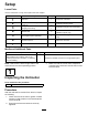
Setup Loose Parts Use the chart below to verify that all parts have been shipped. Procedure Description 1 2 3 4 5 6 7 Use Qty. Verticutter 1 Inspect the verticutter. Transport roller assembly Cotter pin O-ring Straight grease fitting 2 2 1 1 Shoulder bolt 5 Install the shoulder bolt (RM5010–Hybrid only) End-weight kit (sold separately) 1 Install the end-weight kit (Model 03618 only). No parts required – Adjust the verticutter. No parts required – Mount the verticutter reel.
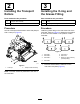
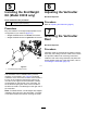
2 3 Installing the Transport Rollers Installing the O-ring and the Grease Fitting Parts needed for this procedure: Parts needed for this procedure: 2 Transport roller assembly 1 O-ring 2 Cotter pin 1 Straight grease fitting Procedure Procedure Secure a transport roller bracket to each side plate pin with a cotter pin (Figure 3). Install the grease fitting on the reel-motor side of the verticutter.
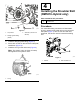
4 Installing the Shoulder Bolt (RM5010–Hybrid only) Parts needed for this procedure: 5 Shoulder bolt Procedure For verticutters being mounted on a Reelmaster 5010-H, replace the shoulder bolt on the reel-motor side-plate (Figure 7) with the new shoulder bolt; otherwise, the electric reel will contact the existing bolt. g028407 Figure 5 1. Cap screws 3. Setscrew (remove and discard) 2. Straight grease fitting (install) 2. Install the straight grease fitting (Figure 5). 3.
5 6 Installing the End-Weight Kit (Model 03618 only) Adjusting the Verticutter No Parts Required Parts needed for this procedure: 1 Procedure End-weight kit (sold separately) Refer to Adjusting the Verticutter (page 9). Procedure 7 Buy and install the end weight kit appropriate for the configuration of your machine (Figure 8).
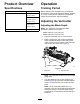
Product Overview Operation Specifications Training Period Model Net weight 03618 With no end weight: Before operating the verticutter reels, evaluate the performance of the reel at the desired setting. Operate in a clear, unused area to determine if the desired results will be achieved. Adjust as desired. 49.4 kg (109 lb) With small end weight (hydraulic motor): Adjusting the Verticutter 52.6 kg (116 lb) With large end weight (electric motor): Adjusting the Blade Depth 55.
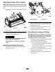
Adjusting the Rear Grass Shield Note: When operating in turf conditions where there is excessive debris or thatch, open the rear discharge shield to help allow the debris to discharge from the reel. 1. Loosen the bolts on the pivot of the grass shield (Figure 10). g028404 Figure 11 1. Front roller scraper 3. Transport roller 2. Rear roller scraper 4. Cotter pin 2. Move the scraper rods in or out to attain 0.0 to 0.75 mm (0.0 to 0.03 inch) clearance between the scraper and roller. 3.
Operating Tips • Operate the traction unit at full throttle, full reel speed (setting 9) and at the desired traction speed. • The maximum recommended blade penetration depths are as follows: – Model 03618 is 3 mm (1/8 inch). – Model 03619 is 6 mm (1/4 inch). • Power requirements to operate the verticutter reels will vary with turf and soil conditions. Travel speed may need to be reduced in some conditions.
Maintenance Lubricating the Verticutter Each verticutter has 5 grease fittings (Figure 13) that must be lubricated weekly with No. 2 lithium grease. Using the Kickstand When Tipping the Cutting Unit The lubrication points are the front roller (2), the rear roller (2), and the reel motor splines (1). Note: Whenever the verticutter has to be tipped to expose the verticutter blades, use the kickstand (supplied with traction unit) (Figure 12).
Removing the Verticutter Blades from the Shaft 1. Secure the end of the verticutter shaft, which has only one washer and nut, in a vise. 2. On other end of shaft, rotate the nut counter-clockwise and remove the nut. Important: The order of disassembly is extremely important. Do not invert the verticutter reel blades when disassembling or reverse the order when assembling them. Note the index hole in each verticutter blade.
Installing the Verticutter Blades 1. Assemble a blade (Figure 16). 2. Assemble a large spacer. 3. Do not invert the reel blades when assembling them on the reel shaft. Note: If you invert the blades, the blades in use (rounded) will mix with the sharp ends of the previously unused blades, resulting in unsatisfactory cutting performance. 4. Install the next blade clockwise so that the index reference hole (Figure 16) is not aligned with the first blade hole by one flat of the shaft.
Optional Blade Spacing 0.50-Inch Blade Spacing for Model 03618 To change the configuration of the verticutter from the standard 0.75-inch spacing to the 0.50-inch spacing requires an additional 34 spacers, Part No. 17-1580 and an additional 10 carbide blades, Part No. 106-6355, or an additional 10 regular blades and Part No. 17-1590 (Figure 17). g345670 Figure 17 2. 1. 0.75-inch blade spacing (default) 0.50-inch blade spacing 1.
Servicing the Roller inner seals, and outer seals to rebuild a roller. The Roller Rebuild Tool Kit includes all the tools and the installation instructions required to rebuild a roller with the roller rebuild kit. Refer to your parts catalog or contact your authorized Toro distributor for assistance. The Roller Rebuild Kit (Part No. 114-5430) and the Roller Rebuild Tool Kit (Part No. 115-0803) (Figure 19) are available for servicing the roller.
Notes:
Declaration of Incorporation The Toro Company, 8111 Lyndale Ave. South, Bloomington, MN, USA declares that the following unit(s) conform(s) to the directives listed, when installed in accordance with the accompanying instructions onto certain Toro models as indicated on the relevant Declarations of Conformity. Model No. Serial No.
EEA/UK Privacy Notice Toro’s Use of Your Personal Information The Toro Company (“Toro”) respects your privacy. When you purchase our products, we may collect certain personal information about you, either directly from you or through your local Toro company or dealer.
The Toro Warranty Two-Year or 1,500 Hours Limited Warranty Parts Conditions and Products Covered The Toro Company warrants your Toro Commercial product (“Product”) to be free from defects in materials or workmanship for 2 years or 1,500 operational hours*, whichever occurs first. This warranty is applicable to all products with the exception of Aerators (refer to separate warranty statements for these products).