Form No. 3395-552 Rev A Verticutter Reelmaster® 5010-H Series Cutting Unit with 5–inch or 7–inch Reel Model No. 03618—Serial No. 315000001 and Up Model No. 03619—Serial No. 315000001 and Up Register at www.Toro.com.
This manual uses 2 words to highlight information. Important calls attention to special mechanical information and Note emphasizes general information worthy of special attention. WARNING CALIFORNIA Proposition 65 Warning This product contains a chemical or chemicals known to the State of California to cause cancer, birth defects, or reproductive harm. This product complies with all relevant European directives. For details, please see the Declaration of Incorporation (DOI) at the back of this publication.
Contents Safety Safety ........................................................................... 3 Safety and Instructional Decals ................................. 4 Setup ............................................................................ 5 1 Inspecting the Verticutter....................................... 6 2 Installing the Transport Rollers ............................... 6 3 Installing the O-ring and the Grease Fitting ................................................................
• Perform only those maintenance procedures described in genuine parts. When it comes to reliability, Toro delivers replacement parts designed to the exact engineering specifications of our equipment. For peace of mind, insist on Toro genuine parts. this manual. If major repairs are ever needed or assistance is desired, contact an Authorized Toro Distributor.
Installation Loose Parts Use the chart below to verify that all parts have been shipped. Procedure Description 1 2 3 4 5 6 7 8 9 10 Use Qty. Verticutter 1 Inspect the verticutter. Transport roller assembly Cotter pin O-ring Straight grease fitting 2 2 1 1 Shoulder bolt 5 Install the shoulder bolt (RM5010–Hybrid only) End-weight kit (sold separately) 1 Install the end-weight kit (Model 03618 only). No parts required – Adjust the blade depth.
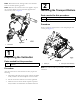
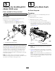
Note: Determine the left and right sides of the machine from the normal operating position. 2 Note: Whenever the verticutter has to be tipped to expose the verticutter blades, use the kickstand (supplied with traction unit); refer to Figure 2. Installing the Transport Rollers Parts needed for this procedure: 2 Transport roller assembly 2 Cotter pin Procedure Secure a transport roller bracket to each side plate pin with a cotter pin (Figure 3). Figure 2 1.
4. Install the O-ring on the reel motor (Figure 6). 3 Note: The electric motor is shown; this step also applies to the hydraulic motor. Installing the O-ring and the Grease Fitting Parts needed for this procedure: 1 O-ring 1 Straight grease fitting Procedure The grease fitting must be installed on the reel motor side of the verticutter. Use the following diagram to determine the position of each reel motor (Figure 4). Figure 6 1.
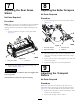
5 6 Installing the End-Weight Kit (Model 03618 only) Adjusting the Blade Depth No Parts Required Parts needed for this procedure: 1 Procedure End-weight kit (sold separately) Note: The maximum recommended blade penetration depths are as follows: Procedure • Model 03618 is 3 mm (1/8 inch). Buy and install the end weight kit appropriate for the configuration of your machine (Figure 8). • Model 03619 is 6 mm (1/4 inch). 1. Place the verticutter reel on a level surface.
7 8 Adjusting the Rear Grass Shield Adjusting the Roller Scrapers No Parts Required Procedure No Parts Required 1. Loosen the flange nuts that secure the roller scrapers (Figure 11). Procedure Note: When operating in turf conditions where much debris or unusually heavy thatch is encountered, open the rear discharge shield to help allow the debris to discharge from the reel. 1. Loosen the bolts on the pivot of the grass shield (Figure 10). Figure 11 1. Front roller scraper 3. Transport roller 2.
Product Overview • Lower the roller bracket before the verticutter is lowered to the shop floor. • Raise the roller bracket after the verticutter is raised Specifications to the operating position. 3. Secure the transport roller bracket to the side plate pin with the cotter pin. Model Net weight 03618 With no end weight: 49.4 kg (109 lb) 4. Repeat the procedure on the opposite end of the verticutter. With small end weight (hydraulic motor): 52.
Operation Note: Determine the left and right sides of the machine from the normal operating position. Training Period Before operating the verticutter reels, evaluate the performance of the reel at the desired setting. Operate in a clear, unused area to determine if the desired results will be achieved. Adjust as desired. Operating Tips 1. Operate the traction unit at full throttle, full reel speed (setting 9) and at the desired traction speed. 2.
Maintenance Removing the Verticutter Blades from the Shaft Lubricating the Verticutter 1. Secure the end of the verticutter shaft, which has only one washer and nut, in a vise. Each verticutter has 5 grease fittings (Figure 12) that must be lubricated weekly with #2 general-purpose, lithium-based grease. 2. On other end of shaft, rotate the nut counter-clockwise and remove the nut. The lubrication points are the front roller (2), the rear roller (2), and the reel motor splines (1).
Installing the Verticutter Blades 1. Assemble a blade (Figure 14). 2. Assemble a large spacer. 3. Do not invert the reel blades when assembling them on the reel shaft. Note: If the blades are inverted, the blades that are in use, (rounded) will be mixed with the sharp ends of the blades which were not in use. This will cause unsatisfactory performance in the verticutter reel unit. Attention should always be taken when disassembling the verticutter blades from reel. 4.
Optional Blade Spacing 0.50-Inch Blade Spacing for Model 03618 To change the configuration of the verticutter from the standard 0.75-inch spacing to the 0.50-inch spacing requires an additional 34 spacers, part no. 17-1580 and an additional 10 carbide blades, part no. 106-6355, or an additional 10 regular blades and part no. 17-1590 (Figure 15). 1 2 Figure 15 1. 0.50-inch spacing 2. 0.75-inch spacing 1.
Servicing the Roller bearings, bearing nuts, inner seals and outer seals to rebuild a roller. The Roller Rebuild Tool Kit includes all the tools and the installation instructions required to rebuild a roller with the roller rebuild kit. Refer to your parts catalog or contact your Authorized Toro Distributor for assistance. A Roller Rebuild Kit, Part No. 114–5430 and a Roller Rebuild Tool Kit, Part No. 115–0803 (Figure 17) are available for servicing the roller.
Notes: 16
Notes: 17
Declaration of Incorporation Model No. Serial No. Product Description 03618 315000001 and Up Verticutter 03619 315000001 and Up Verticutter Invoice Description 22IN 5IN VERTICUTTER [5010 HYBRID] 22IN 7IN VERTICUTTER [5010 HYBRID] General Description Directive Verticutter 2006/42/EC Verticutter 2006/42/EC Relevant technical documentation has been compiled as required per Part B of Annex VII of 2006/42/EC.
International Distributor List Distributor: Country: Phone Number: Distributor: Phone Number: 57 1 236 4079 Colombia Japan 81 3 3252 2285 Czech Republic 420 255 704 220 420 255 704 Slovakia 220 Argentina 54 11 4 821 9999 Russia 7 495 411 61 20 Ecuador 593 4 239 6970 Finland 358 987 00733 Agrolanc Kft Balama Prima Engineering Equip. B-Ray Corporation Hungary Hong Kong Korea 36 27 539 640 852 2155 2163 82 32 551 2076 Maquiver S.A. Maruyama Mfg. Co. Inc. Mountfield a.s.
Toro General Commercial Product Warranty A Two-Year Limited Warranty Conditions and Products Covered The Toro Company and its affiliate, Toro Warranty Company, pursuant to an agreement between them, jointly warrant your Toro Commercial product (“Product”) to be free from defects in materials or workmanship for two years or 1500 operational hours*, whichever occurs first. This warranty is applicable to all products with the exception of Aerators (refer to separate warranty statements for these products).