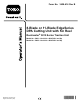
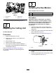
Form No. 3428-616 Rev B 8-Blade or 11-Blade EdgeSeries DPA Cutting Unit with 5in Reel Reelmaster® 5010 Series Traction Unit Model No. 03621—Serial No. 403470001 and Up Model No. 03623—Serial No. 403470001 and Up Register at www.Toro.com.
This product complies with all relevant European directives. For details, please see the Declaration of Incorporation (DOI) at the back of this publication. Introduction This cutting unit is designed for cutting grass on well-maintained lawns in golf courses, parks, sports fields, and on commercial grounds. Using this product for purposes other than its intended use could prove dangerous to you and bystanders.
Contents Safety Safety ....................................................................... 3 General Safety ................................................... 3 Cutting Unit Safety.............................................. 3 Blade Safety ....................................................... 4 Safety and Instructional Decals .......................... 4 Setup ........................................................................ 5 1 Installing the Reel Grease Fitting......................
• Inspect the blade periodically for wear or damage. • Keep all parts in good working condition and all hardware tightened. Replace all worn or damaged decals. • Use care when checking the blades. Wrap the blades or wear gloves, and use caution when servicing the blades. Only replace or sharpen the blades; never straighten or weld them. • Use only accessories, attachments, and replacement parts approved by Toro. • On multi-bladed machines, take care as rotating 1 blade can cause other blades to rotate.
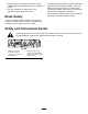
Setup Loose Parts Use the chart below to verify that all parts have been shipped. Procedure 1 2 3 Description Use Qty. Straight grease fitting 1 Install the reel grease fitting. No parts required – Adjust the cutting unit O-ring Cap screws (may come assembled) 1 2 Install the reel motors. Media and Additional Parts Description Qty.
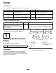
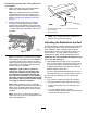
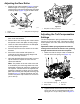
3 Installing the Reel Motors Parts needed for this procedure: g031255 Figure 4 1. Cap screw (2) 3. Grease fitting 2. Setscrew 4. Grease vent 2. 1 O-ring 2 Cap screws (may come assembled) Procedure Important: Before installing the reel motors, obtain and install the counter weights or other accessories on the opposite side of the cutting units from the reel motors as described in the instructions provided with the weights or accessories. Install the straight grease fitting (Figure 4). 2 1.
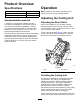
Product Overview Operation Specifications Model Number Weight 03621 51 kg (112 lb) 03623 52 kg (116 lb) Note: Determine the left and right sides of the machine from the normal operating position. Adjusting the Cutting Unit Attachments/Accessories Adjusting the Rear Shield A selection of Toro approved attachments and accessories is available for use with the machine to enhance and expand its capabilities. Contact your Authorized Service Dealer or authorized Toro distributor or go to www.Toro.
Perform this procedure even if the quality of cut is acceptable. 1. Slowly rotate the reel in a reverse direction, listening for reel-to-bedknife contact. Note: The adjustment knobs have detents corresponding to 0.018 mm (0.0007 inch) bedknife movement for each indexed position. Refer to Adjusting the Bedknife to the Reel (page 8). 2. Test the cutting performance by inserting a long strip of cutting performance paper (Part No.
Note: If starting with a large gap, both sides should initially be drawn closer by alternately tightening the right and left sides. 7. Slowly rotate the reel so that the same blade that you checked on the right side is crossing the bedknife approximately 25 mm (1 inch) in from the end of the bedknife on the left side of the cutting unit. 8. Turn the left bedbar adjuster clockwise until the shim can be slid through the reel to bedknife gap with light drag. 9.
Adjusting the Rear Roller 1. Adjust the rear roller brackets (Figure 12) to the desired height-of-cut range by positioning the required amount of spacers below the side-plate mounting flange (Figure 12) per the HOC Chart. g011862 Figure 13 g003324 1. Side-plate mounting cap screws Figure 12 1. Spacer 3. Side-plate mounting flange 2. Roller bracket 2. Raise the rear of the cutting unit and place a block under the bedknife. 3.
Note: When operating on rough terrain decrease the spring length by 1.3 cm (1/2 inch). Ground following will be slightly decreased. Note: You will need to reset the turf compensation setting if the HOC setting or the aggressiveness-of-cut setting is changed. Adjusting the Height of Cut (HOC) g003327 Figure 16 Note: For heights of cut greater than 2.54 cm (1 inch) install the High Height-of-Cut Kit. 1. Loosen the locknuts securing the height-of-cut brackets to the cutting-unit side plates (Figure 15).
Height-of-Cut Chart HOC Setting Aggressiveness of Cut No. of Rear Spacers No. of Chain Links With Groomer kits installed** 0.64 cm (0.250 inches) Less Normal More 0 0 1 3+ 3+ 3 Y Y - 0.95 cm (0.375 inches ) Less Normal More 0 1 2 4 3 3 Y Y - 1.27 cm (0.500 inches) Less Normal More 0 1 2 4 3+ 3 Y Y Y 1.56 cm (0.625 inches) Less Normal More 1 2 3 4 3 3 Y Y - 1.91 cm (0.750 inches) Less Normal More 2 3 4 3+ 3 3 Y Y - 2.22 cm (0.
Use the following chart to determine which bedknife is best suited for the desired height of cut. Bedknife/Height of Cut Chart Bedknife Part No. Bedknife Lip Height Height of Cut Low HOC (Optional) 110-4084 5.6 mm (0.220 inch) 6.4 to 12.7 mm (0.250 to 0.500 inch) EdgeMax® Low HOC (Model 03623) 137-0832 5.6 mm (0.220 inch) 6.4 to 12.7 mm (0.250 to 0.500 inch) Extended Low HOC (Optional) 120-1640 5.6 mm (0.220 inch) 6.4 to 12.7 mm (0.250 to 0.
g033036 Figure 19 1. Rear spacers 3. Aggressiveness of cut 2. Side-plate mounting flange Rear Spacers The number of rear spacers determines the aggressiveness of cut for the cutting unit. For a given height of cut, adding spacers below the side-plate mounting flange increases the aggressiveness of the cutting unit. All cutting units on a given machine must be set to the same aggressiveness of cut (number of rear spacers, Part No.
Maintenance Using the Kickstand When Tipping the Cutting Unit Whenever the cutting unit has to be tipped to expose the bedknife/reel, prop up the rear of the cutting unit with the kickstand (supplied with the traction unit) to make sure that the nuts on the back end of the bedbar adjusting screws are not resting on the work surface (Figure 21). g027267 Figure 22 Grease fitting locations on left side Relief-Grinding the Reel The reel has a land width of 1.3 to 1.5 mm (0.050 to 0.
g028838 Figure 24 Model 03623 1. 1.3 mm (0.050 inch) 2. 2. 30 degrees Spin grind the reel to achieve <0.025 mm (0.001 inch) reel run-out. Note: This causes the land width to grow slightly. Note: To extend the longevity of the sharpness of the edge of the reel and the bedknife—after grinding the reel and/or the bedknife—check the reel-to-bedknife contact again after cutting 2 fairways, as any burrs will be removed, which may create improper reel-to-bedknife clearance and thus accelerate wear.
Servicing the Bedknife The bedknife service limits are listed in the following chart. Important: Operating the cutting unit with the bedknife below the service limit may result in poor after-cut appearance and reduce the structural integrity of the bedknife for impacts. Bedknife Service Limit Chart Bedknife Part No. Bedknife Lip Height* Service Limit* Low HOC (Optional) 110-4084 5.6 mm (0.220 inch) 4.8 mm (0.190 inch) 10/5 Degrees EdgeMax® Low HOC (Model 03623) 137-0832 5.6 mm (0.220 inch) 4.
Servicing the Bedbar Removing the Bedbar 1. Turn the bedbar-adjusting screws counterclockwise to back the bedknife away from the reel (Figure 29). g034113 Figure 27 2. Angle indicator 1. Bedknife (vertical) 2. Press the Alt Zero button on the angle indicator. 3. Place the angle-indicator mount on the edge of the bedknife so that the edge of the magnet is mated with the edge of the bedknife (Figure 28).
2. Clean the screw threads. 3. Apply anti-seize compound to the screws and install the bedknife to the bedbar as follows (Figure 33): g027176 Figure 31 1. Bedbar bolt 2. Nut 3. Steel washer 4. Nylon washer Assembling the Bedbar 1. Install the bedbar, positioning the mounting ears between the washer and the bedbar adjuster. 2. Secure the bedbar to each side plate with the bedbar bolts (nuts on bolts) and the 6 washers. Note: Position a nylon washer on the each side of the side-plate boss.
9. Secure the bedbar to each side plate with the bedbar bolts (nuts on bolts) and 6 washers as follows: A. Position a nylon washer on each side of the side-plate boss. B. Place a steel washer outside each of the nylon washers (Figure 35). C. Torque the bedbar bolts to 37 to 45 N∙m (27 to 33 ft-lb). D. Tighten the locknuts until the outside steel washer stops rotating and end play is removed, but do not overtighten or deflect the side plates.
g016355 Figure 35 2. Wave washer 4. Apply anti-seize compound here. 5. Flat washer 7. Apply anti-seize compound 10. Compression spring here. 8. Bedbar-adjuster screw 11. Spring-tension nut 3. Flange bushing 6. Locknut 9. Hardened washer 1.
Servicing the Roller inner seals, and outer seals to rebuild a roller. The Roller Rebuild Tool Kit includes all the tools and the installation instructions required to rebuild a roller with the Roller Rebuild Kit. Refer to your Parts Catalog or contact your distributor for assistance. A Roller Rebuild Kit, Part No. 114-5430 and a Roller Rebuild Tool Kit, Part No. 115-0803 (Figure 36) are available for servicing the roller.
Notes:
Notes:
Notes:
Declaration of Incorporation The Toro Company, 8111 Lyndale Ave. South, Bloomington, MN, USA declares that the following unit(s) conform(s) to the directives listed, when installed in accordance with the accompanying instructions onto certain Toro models as indicated on the relevant Declarations of Conformity. Model No. Serial No.
EEA/UK Privacy Notice Toro’s Use of Your Personal Information The Toro Company (“Toro”) respects your privacy. When you purchase our products, we may collect certain personal information about you, either directly from you or through your local Toro company or dealer.
The Toro Warranty Two-Year or 1,500 Hours Limited Warranty Conditions and Products Covered Parts The Toro Company and its affiliate, Toro Warranty Company, pursuant to an agreement between them, jointly warrant your Toro Commercial product (“Product”) to be free from defects in materials or workmanship for 2 years or 1,500 operational hours*, whichever occurs first. This warranty is applicable to all products with the exception of Aerators (refer to separate warranty statements for these products).