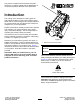
Form No. 3438-172 Rev A 8-Blade Forward Swept Reel, 11-Blade Radial Reel, or 11-Blade Forward Swept EdgeSeries™ DPA Cutting Unit with 5in Reel Reelmaster® 5010 Series Traction Unit Model No. 03621—Serial No. 405700000 and Up Model No. 03623—Serial No. 405700000 and Up Model No. 03624—Serial No. 400000000 and Up Register at www.Toro.com.
This product complies with all relevant European directives. For details, please see the Declaration of Incorporation (DOI) at the back of this publication. Introduction This cutting unit is designed for cutting grass on well-maintained lawns in golf courses, parks, sports fields, and on commercial grounds. Using this product for purposes other than its intended use could prove dangerous to you and bystanders.
Contents Safety Safety ....................................................................... 3 General Safety ................................................... 3 Cutting Unit Safety.............................................. 4 Blade Safety ....................................................... 4 Safety and Instructional Decals .......................... 4 Setup ........................................................................ 5 1 Installing the Reel Grease Fitting......................
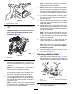
Cutting Unit Safety Blade Safety • The cutting unit is only a complete machine when A worn or damaged blade can break, and a piece of the blade could be thrown toward you or bystanders, resulting in serious personal injury or death. installed on a traction unit. Read the traction unit Operator’s Manual carefully for complete instructions on the safe use of the machine. • Inspect the blade periodically for wear or damage.
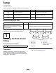
Setup Loose Parts Use the chart below to verify that all parts have been shipped. Procedure 1 2 3 Description Use Qty. Straight grease fitting 1 Install the reel grease fitting. No parts required – Adjust the cutting unit O-ring Cap screws (may come assembled) 1 2 Install the reel motors. Media and Additional Parts Description Qty.
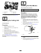
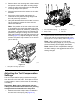
3 Installing the Reel Motors Parts needed for this procedure: g031255 Figure 4 1. Cap screw (2) 3. Grease fitting 2. Setscrew 4. Grease vent 2. 1 O-ring 2 Cap screws (may come assembled) Procedure Important: Before installing the reel motors, obtain and install the counter weights or other accessories on the opposite side of the cutting units from the reel motors as described in the instructions provided with the weights or accessories. Install the straight grease fitting (Figure 4). 2 1.
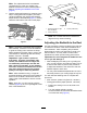
Product Overview Operation Specifications Refer to your traction unit Operator’s Manual for detailed operation instructions. Before using the cutting unit each day, adjust the bedknife; refer to Adjusting the Bedknife to the Reel (page 8). Test the quality of cut by cutting a test swath before using the cutting unit to ensure that the finished cut is correct.
Note: The adjustment knobs have detents corresponding to 0.018 mm (0.0007 inch) bedknife movement for each indexed position. Refer to Adjusting the Bedknife to the Reel (page 8). 2. Test the cutting performance by inserting a long strip of cutting performance paper (Toro Part 125-5610) between the reel and the bedknife, perpendicular to the bedknife (Figure 7). Slowly rotate the reel forward; it should cut the paper. g031270 Figure 8 1. Lead-in chamfer on right end of bedknife 2. 6 mm (0.25 inch) 3. 1.
Note: If starting with a large gap, both sides should initially be drawn closer by alternately tightening the right and left sides. 7. Slowly rotate the reel so that the same blade that you checked on the right side is crossing the bedknife approximately 25 mm (1 inch) in from the end of the bedknife on the left side of the cutting unit. 8. Turn the left bedbar adjuster clockwise until the shim can be slid through the reel to bedknife gap with light drag. 9.
3. Remove the 2 nuts securing each roller bracket and spacer to each side-plate mounting flange. 4. Lower the roller and screws from the side-plate mounting flanges and spacers. 5. Place the spacers onto the screws on the roller brackets. 6. Secure the roller bracket and spacers to underside of side plate mounting flanges with the nuts previously removed. 7. Verify that the bedknife-to-reel contact is correct. Tip the mower to expose the front and rear rollers and bedknife.
Adjusting the Height of Cut (HOC) ends of roller until the entire roller is parallel to the bedknife. Note: For heights of cut greater than 2.54 cm (1 inch) install the High Height-of-Cut Kit. 1. Loosen the locknuts securing the height-of-cut brackets to the cutting-unit side plates (Figure 14). g027266 Figure 16 Important: When set properly, the rear and front rollers will contact the gauge bar and the screw will be snug against the bedknife.
Height-of-Cut Chart HOC Setting Aggressiveness of Cut No. of Rear Spacers No. of Chain Links With Groomer kits installed** 0.64 cm (0.250 inches) Less Normal More 0 0 1 3+ 3+ 3 Y Y - 0.95 cm (0.375 inches ) Less Normal More 0 1 2 4 3 3 Y Y - 1.27 cm (0.500 inches) Less Normal More 0 1 2 4 3+ 3 Y Y Y 1.56 cm (0.625 inches) Less Normal More 1 2 3 4 3 3 Y Y - 1.91 cm (0.750 inches) Less Normal More 2 3 4 3+ 3 3 Y Y - 2.22 cm (0.
Use the following chart to determine which bedknife is best suited for the desired height of cut. Bedknife/Height of Cut Chart Bedknife Part No. Bedknife Lip Height Height of Cut Low HOC (Model 03624) 110-4084 5.6 mm (0.220 inch) 6.4 to 12.7 mm (0.250 to 0.500 inch) EdgeMax® Low HOC (Model 03623) 137-0832 5.6 mm (0.220 inch) 6.4 to 12.7 mm (0.250 to 0.500 inch) Extended Low HOC (Optional) 120-1640 5.6 mm (0.220 inch) 6.4 to 12.7 mm (0.250 to 0.
Height-of-Cut Chart Terms Height-of-Cut Setting (HOC) This corresponds to the desired height of cut. Bench-Set Height of Cut The bench-set height of cut is the height at which the top edge of the bedknife is set above a flat level surface that contacts the bottom of both the front roller and the rear roller. g033036 Figure 18 1. Rear spacers 3. Aggressiveness of cut 2. Side-plate mounting flange Effective Height of Cut This is the actual height that the grass has been cut.
Maintenance Lubricating the Cutting Units Using the Kickstand when Tipping the Cutting Unit Regularly lubricate the 5 grease fittings of each cutting unit (Figure 21) with No. 2 lithium grease. There are 2 lubrication points on the front roller, 2 on the rear roller, and 1 at the reel-motor spline.
Relief-Grinding the Reel Note: To extend the longevity of the sharpness of the edge of the reel and the bedknife—after grinding the reel and/or the bedknife—check the reel to bedknife contact again after cutting 2 fairways, as any burrs will be removed, which may create improper reel to bedknife clearance and thus accelerate wear. The new reel has a land width of 1.3 to 1.5 mm (0.050 to 0.060 inch) and a 30° relief grind. When the land width gets larger than 3 mm (0.120 inch) wide, do the following: 1.
Servicing the Bedknife The bedknife service limits are listed in the following chart. Important: Operating the cutting unit with the bedknife below the service limit may result in poor after-cut appearance and reduce the structural integrity of the bedknife for impacts. Bedknife Service Limit Chart Bedknife Part No. Bedknife Lip Height* Service Limit* Low HOC (Model 03624) 110-4084 5.6 mm (0.220 inch) 4.8 mm (0.190 inch) 10/5 Degrees EdgeMax® Low HOC (Model 03623) 137-0832 5.6 mm (0.
Servicing the Bedbar Removing the Bedbar 1. Turn the bedbar-adjusting screws counterclockwise to back the bedknife away from the reel (Figure 28). g034113 Figure 26 2. Angle indicator 1. Bedknife (vertical) 2. Press the Alt Zero button on the angle indicator. 3. Place the angle-indicator mount on the edge of the bedknife so that the edge of the magnet mates with the edge of the bedknife (Figure 27).
Installing the Bedknife 1. Remove the rust, scale, and corrosion from the bedbar surface and apply a thin layer of oil to the bedbar surface. 2. Clean the screw threads. 3. Apply anti-seize compound to the screws and install the bedknife to the bedbar as follows (Figure 32): g003335 Figure 30 1. Bedbar bolt 2. Nut 3. Steel washer 4. Nylon washer Assembling the Bedbar 1. Install the bedbar, positioning the mounting ears between the washer and the bedbar adjuster. 2.
Servicing the HD Dual Point Adjusters (DPA) g279162 Figure 33 1. Bedknife screw tool 3. Torque to 23 to 28 N∙m (200 to 250 in-lb). 2. Install and torque these first to 1 N∙m (10 in-lb). 4. 1. Remove all parts (refer to the Installation Instructions for the HD DPA Kit and to Figure 34). 2. Apply anti-seize compound to the inside of the bushing area on cutting unit center frame (Figure 34). 3. Align the keys on flange bushings to the slots in the frame and install the bushings (Figure 34). 4.
7. Apply anti-seize compound to the threads of the bedbar-adjuster screw that fit into the adjuster shaft. 8. Thread the bedbar-adjuster screw into the adjuster shaft. 9. Loosely install the hardened washer, spring, and spring tension nut onto the adjuster screw. 10. Install the bedbar, positioning the mounting ears between the washer and the bedbar adjuster. 11. Secure the bedbar to each side plate with the bedbar bolts (nuts on bolts) and 6 washers.
Servicing the Roller inner seals, and outer seals to rebuild a roller. The Roller Rebuild Tool Kit includes all the tools and the installation instructions required to rebuild a roller with the roller rebuild kit. Refer to your parts catalog or contact your authorized Toro distributor for assistance. The Roller Rebuild Kit (Part No. 114-5430) and the Roller Rebuild Tool Kit (Part No. 115-0803) (Figure 35) are available for servicing the roller.
Notes:
Notes:
Notes:
Declaration of Incorporation The Toro Company, 8111 Lyndale Ave. South, Bloomington, MN, USA declares that the following unit(s) conform(s) to the directives listed, when installed in accordance with the accompanying instructions onto certain Toro models as indicated on the relevant Declarations of Conformity. Model No. Serial No.
EEA/UK Privacy Notice Toro’s Use of Your Personal Information The Toro Company (“Toro”) respects your privacy. When you purchase our products, we may collect certain personal information about you, either directly from you or through your local Toro company or dealer.
The Toro Warranty Two-Year or 1,500 Hours Limited Warranty Conditions and Products Covered Parts The Toro Company and its affiliate, Toro Warranty Company, pursuant to an agreement between them, jointly warrant your Toro Commercial product (“Product”) to be free from defects in materials or workmanship for 2 years or 1,500 operational hours*, whichever occurs first. This warranty is applicable to all products with the exception of Aerators (refer to separate warranty statements for these products).