
Operator's Manual

3.Removethe2nutssecuringeachrollerbracket
andspacertoeachside-platemountingange.
4.Lowertherollerandscrewsfromtheside-plate
mountingangesandspacers.
5.Placethespacersontothescrewsontheroller
brackets.
6.Securetherollerbracketandspacersto
undersideofsideplatemountingangeswith
thenutspreviouslyremoved.
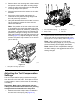
7.Verifythatthebedknife-to-reelcontactiscorrect.
Tipthemowertoexposethefrontandrear
rollersandbedknife.
Note:Thepositionoftherearrollertothereel
iscontrolledbythemachiningtolerancesofthe
assembledcomponents;therefore,parallelingis
notrequired.Alimitedamountofadjustmentis
possiblebysettingthecuttingunitonasurface
plateandlooseningtheside-platemountingcap
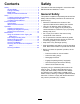
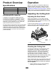
screws(Figure12).Adjustandtightenthecap
screws.T orquethecapscrewsto37to45N·m
(27to33ft-lb).
g011862
Figure12
1.Side-platemountingcapscrews
AdjustingtheTurf-Compensation
Settings
Theturf-compensationspringtransferstheweight
fromthefronttotherearroller.Thishelpstoreduce
awavepatternintheturf,alsoknownasmarcelling
orbobbing.
Important:Makespringadjustmentswiththe
cuttingunitmountedtothetractionunit,pointing
straightaheadandloweredtotheshopoor.
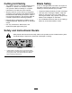
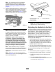
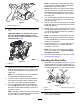
1.Makesurethatthehairpincotterisinstalledin
therearholeinthespringrod(Figure13).
g027263
Figure13
1.Turf-compensationspring3.Springrod
2.Hairpincotter4.Hexnuts
2.Tightenthehexnutsonthefrontendofthe
springroduntilthecompressedlengthofthe
springis12.7cm(5inches);refertoFigure13.
Note:Whenoperatingonroughterrain
decreasethespringlengthby1.3cm(1/2inch).
Groundfollowingwillbeslightlydecreased.
Note:Resettheturfcompensationsettingif
theHOCsettingortheaggressiveness-of-cut
settingchanges.
10