
Operator's Manual


g003335
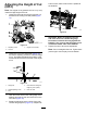
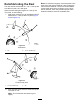
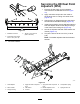
Figure30
1.Bedbarbolt
3.Steelwasher
2.Nut4.Nylonwasher
AssemblingtheBedbar
1.Installthebedbar,positioningthemountingears
betweenthewasherandthebedbaradjuster.
2.Securethebedbartoeachsideplatewiththe
bedbarbolts(nutsonbolts)andthe6washers.
Note:Positionanylonwasherontheeachside
oftheside-plateboss.Placeasteelwasher
outsideoftheouternylonwashers(Figure30).
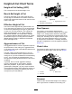
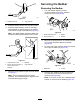
3.T orquethebedbarboltsto27to36N∙m(240
to320in-lb).
4.Tightenthelocknutsequallyoneachsideuntil
theoutersteelwasherscannotberotatedby
hand.Thenloosenthelocknutsuntiltheouter
steelwashersjustrotatebyhand,yetthereisno
bedbarendplay(Figure31).
Note:Overtighteningthelocknutscandeect
thesideplatesandthebedbar,whichcanaffect
reel-to-bedknifecontact.
Note:Thewashersontheinsidemayhavea
gap.
Note:Donotovertightenthenuts,asdamage
tothespringmayoccur.
g006505
Figure31
1.Spring-tensionnut2.Spring
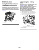
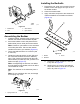
InstallingtheBedknife
1.Removetherust,scale,andcorrosionfromthe
bedbarsurfaceandapplyathinlayerofoilto
thebedbarsurface.
2.Cleanthescrewthreads.
3.Applyanti-seizecompoundtothescrewsand
installthebedknifetothebedbarasfollows
(Figure32):
g279161
Figure32
1.Bedbar
3.Screw
2.Bedknife
A.T orquethe2outerscrewsto1N∙m(10
in-lb);refertoFigure33.
B.Workingformthecenterofthebedknife,
torquethescrewsto23to28N∙m(200to
250in-lb);refertoFigure33.
19