Form No. 3420-472 Rev A 8-Blade Radial Reel, 8-Blade Forward Swept Reel, or 11-Blade Forward Swept Reel DPA Cutting Unit with 7in Reel Reelmaster® 5010-H Series Traction Unit Model No. 03638—Serial No. 400000000 and Up Model No. 03639—Serial No. 400000000 and Up Model No. 03641—Serial No. 400000000 and Up Register at www.Toro.com.
WARNING CALIFORNIA Proposition 65 Warning This product contains a chemical or chemicals known to the State of California to cause cancer, birth defects, or reproductive harm. This product complies with all relevant European directives. For details, please see the Declaration of Incorporation (DOI) at the back of this publication. g027159 Figure 1 1. Location of the model and serial numbers Introduction Important: To maximize the safety, performance, Model No.
Safety This manual identifies potential hazards and has safety messages identified by the safety-alert symbol (Figure 2), which signals a hazard that may cause serious injury or death if you do not follow the recommended precautions. This machine has been designed in accordance with EN ISO 5395:2013. Improper use or maintenance of this equipment can result in injury or death. To reduce the potential for injury or death, comply with the following safety instructions.
Safety and Instructional Decals Safety decals and instructions are easily visible to the operator and are located near any area of potential danger. Replace any decal that is damaged or missing. decal93-6688 93-6688 1. Warning—read the instructions before servicing or performing maintenance. 2. Cutting hazard of hand or foot—shut off the engine and wait for moving parts to stop.
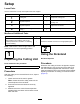
Setup Loose Parts Use the chart below to verify that all parts have been shipped. Procedure Description 1 2 3 4 Use Qty. Cutting unit 1 Inspect the cutting unit. No parts required – Use the kickstand when tipping the cutting unit. No parts required – Adjust the rear shield. Straight grease fitting O-ring 1 1 Install the loose parts. Media and Additional Parts Description Qty.
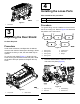
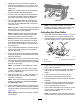
4 Installing the Loose Parts Parts needed for this procedure: g027160 1 Straight grease fitting 1 O-ring Figure 3 1. Kickstand Procedure The grease fitting must be installed on the reel-motor side of the cutting unit. Refer to Figure 5 to determine the position of the reel motors. 3 Adjusting the Rear Shield No Parts Required Procedure g031275 Figure 5 Under most conditions, best dispersion is attained when the rear shield is closed (front discharge).
2. Install the straight grease fitting (Figure 6). 3. If there are no cap screws on the reel-motor side plate, install them (Figure 6). 4. Install the O-ring on the reel motor (Figure 7). g033964 Figure 7 1. O-ring 5. Install the reel motor, and grease the side plate until excess grease comes out of the grease vent (Figure 6).
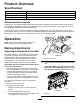
Product Overview Specifications Cutting Unit Weight 03638 54 kg (118 lb) 03639 54 kg (118 lb) 03641 55 kg (121 lb) Attachments/Accessories A selection of Toro-approved attachments and accessories is available for use with the machine to enhance and expand its capabilities. Contact your Authorized Service Dealer or Distributor or go to www.Toro.
4. Rotate the reel so that a blade crosses the bedknife approximately 25 mm (1 inch) in from the end of the bedknife on the right side of the cutting unit. Note: Put an identifying mark on this blade to make subsequent adjustments easier. 5. Insert the 0.05 mm (0.002 inch) shim between the marked reel blade and the bedknife at the point where the blade crosses the bedknife. 6. Turn the right bedbar adjuster clockwise until you feel light pressure (i.e.
of cut refers to the angle of the bedknife relative to the ground (Figure 13). assembled components, and so paralleling is not required. A limited amount of adjustment is possible by setting the cutting unit on a surface plate and loosening the side-plate mounting cap screws (Figure 12). The best cutting unit setup is dependent on your turf conditions and desired results. Experience with the cutting unit on your turf will determine the best setting to use.
g027170 Figure 14 1. Lift chain 2. U-backet 3. Bottom hole Groomer These are the recommended height-of-cut settings when a groomer kit is installed on the cutting unit.
Height-of-Cut Chart These are the recommended height-of-cut settings when a groomer kit is installed on the cutting unit. HOC Setting Aggressiveness of Cut No. of Rear Spacers No. of Chain Links With Groomer kits installed** 0.64 cm (0.250 inch) Less Normal More 0 0 1 5 5 5 Y Y - 0.95 cm (0.375 inch) Less Normal More 0 1 2 5 5 5 Y Y - 1.27 cm (0.500 inch) Less Normal More 0 1 2 5 5 5 Y Y Y 1.56 cm (0.625 inch) Less Normal More 1 2 3 5 5 5 Y Y - 1.91 cm (0.
Adjusting the Height of Cut (HOC) Note: For heights of cut greater than 2.54 cm (1.00 inch) the High Height-of-Cut Kit must be installed. 1. Loosen the locknuts securing the height-of-cut arms to the cutting-unit side plates (Figure 15). g027172 Figure 17 g027171 Figure 15 1. Adjusting screw 3. Height-of-cut arm 6. 2. Locknut 2. Adjust both ends of the roller until the entire roller is parallel to the bedknife.
Use the following chart to determine which bedknife is best suited for the desired height of cut. Bedknife/Height of Cut Chart Bedknife Part No. Bedknife Lip Height Height of Cut Low HOC (Optional) 110-4084 5.6 mm (0.220 inch) 6.4 to 12.7 mm (0.250 to 0.500 inch) EdgeMax® Low HOC (Model 03641) 137-0832 5.6 mm (0.220 inch) 6.4 to -12.7 mm (0.250 to 0.500 inch) Extended Low HOC (Optional) 120-1640 5.6 mm (0.220 inch) 6.4 to 12.7 mm (0.250 to 0.
Checking and Adjusting the Cutting Unit Note: After extended running, a ridge will eventually develop at both ends of the bedknife. Round off or file these notches flush with the cutting edge of the bedknife to ensure smooth operation. The dual knob bedknife-to-reel adjustment system incorporated in this cutting unit simplifies the adjustment procedure needed to deliver optimum mowing performance.
Maintenance Lubricating the Cutting Units Each cutting unit has 5 grease fittings (Figure 22) that must be lubricated regularly with No. 2 lithium grease. There are 2 lubrication points on the front roller, rear roller, and 1 at the reel motor spline. Note: Lubricating cutting units immediately after washing helps purge water out of the bearings and increases bearing life. 1. Wipe each grease fitting with a clean rag. 2.
Servicing the Bedknife The bedknife service limits are listed in the following chart. Important: Operating the cutting unit with the bedknife below the service limit may result in poor after-cut appearance and reduce the structural integrity of the bedknife for impacts. Bedknife Service Limit Chart Bedknife Part Bedknife Lip Height * Service Limit * EdgeMax® Low HOC (Model 03641) 137-0832 5.6 mm (0.220 inch) 6.4-12.7 mm (0.250-0.500 inch) 10/5 Degrees Low HOC (Optional) 110-4084 5.6 mm (0.
Servicing the Bedbar Removing the Bedbar 1. Turn the bedbar-adjusting screws counterclockwise to back the bedknife away from the reel (Figure 29). g034113 Figure 27 2. Angle indicator 1. Bedknife (vertical) 2. Press the Alt Zero button on the angle indicator. 3. Place the angle-indicator mount on the edge of the bedknife so that the edge of the magnet mates with the edge of the bedknife (Figure 28).
g027176 Figure 31 1. Bedbar bolt 2. Nut 3. Steel washer 4. Nylon washer Assembling the Bedbar 1. Install the bedbar, positioning the mounting ears between the washer and bedbar adjuster. 2. Secure the bedbar to each side plate with the bedbar bolts (nuts on bolts) and the 6 washers. Note: Position a nylon washer on each side of the side-plate boss. Place a steel washer outside each of the nylon washers (Figure 31). 3. Torque the bedbar bolts to 37 to 45 N∙m (27 to 33 ft-lb).
Servicing the HD Dual Point Adjusters (DPA) 1. 2. 3. Remove all parts (refer to the Installation Instructions for the HD DPA Kit and to Figure 33). Apply anti-seize compound to the inside of the bushing area on cutting unit center frame (Figure 33). Align the keys on flange bushings to the slots in the frame and install the bushings (Figure 33). 4. Install a wave washer onto the adjuster shaft and slide the adjuster shaft into the flange bushings in the frame of the cutting unit (Figure 33). 5.
16. Repeat this procedure on the other end of the cutting unit. 17. Adjust the bedknife to the reel; refer to Adjusting the Bedknife to the Reel (page 8).
Servicing the Roller nuts, inner seals and outer seals to rebuild a roller. The Roller Rebuild Tool Kit includes all the tools and the installation instructions required to rebuild a roller with the roller rebuild kit. Refer to your Parts Catalog or contact your Authorized Distributor for assistance. The roller Rebuild Kit and the Roller Rebuild Tool Kit (Figure 34) are available for servicing the roller. The Roller Rebuild Kit includes all the bearings, bearing g007790 Figure 34 1.
Notes:
Notes:
Notes:
Declaration of Incorporation The Toro Company, 8111 Lyndale Ave. South, Bloomington, MN, USA declares that the following unit(s) conform(s) to the directives listed, when installed in accordance with the accompanying instructions onto certain Toro models as indicated on the relevant Declarations of Conformity. Model No. Serial No.
European Privacy Notice The Information Toro Collects Toro Warranty Company (Toro) respects your privacy. In order to process your warranty claim and contact you in the event of a product recall, we ask you to share certain personal information with us, either directly or through your local Toro company or dealer. The Toro warranty system is hosted on servers located within the United States where privacy law may not provide the same protection as applies in your country.
The Toro Warranty A Two-Year Limited Warranty Conditions and Products Covered The Toro Company and its affiliate, Toro Warranty Company, pursuant to an agreement between them, jointly warrant your Toro Commercial product (“Product”) to be free from defects in materials or workmanship for two years or 1500 operational hours*, whichever occurs first. This warranty is applicable to all products with the exception of Aerators (refer to separate warranty statements for these products).